
Aeroengine main combustion chamber based on plasma jet ignition and combustion

An aero-engine and plasma technology, which is applied in the direction of rocket engine devices, engine ignition, engine components, etc., can solve the problem of no igniter, integration of fuel injector and combustion chamber, large flow loss of air entering the combustion chamber, and large combustion chamber volume. and weight increase, to achieve good high-altitude ignition performance, shorten ignition delay time, and reduce volume and weight

Active Publication Date: 2019-05-03
AIR FORCE UNIV PLA
View PDF8 Cites 1 Cited by
  • Summary
  • Abstract
  • Description
  • Claims
  • Application Information

AI Technical Summary

Problems solved by technology

[0003] 1. The swirler at the head of the main combustion chamber of a traditional aero-engine promotes the rotation of the incoming air, reduces the flow velocity, and causes a large flow loss of the airflow entering the combustion chamber;
[0004] 2. The volume of the combustion area produced by the swirler is relatively large, and the airflow entering from the main combustion hole on the rear side of the combustion chamber is large, which increases the length of the combustion chamber, resulting in a substantial increase in the volume and weight of the combustion chamber;
[0005] 3. The ignition energy of the spark plug is small, and the mixture cannot be ignited smoothly under many conditions, especially at high altitudes, where the ignition boundary is small and the ignition success rate is low;
[0006] 4. Due to the small flame propagation velocity and the fast airflow propagation velocity, the flame is stabilized by the backflow boundary during ignition and combustion, and the airflow loss is further increased
[0011] GE Corporation of the United States, Siemens Engine Precision Systems Corporation, and Aviation Plasma Technology Corporation applied for a number of patents after 1992 on the main combustion chamber or afterburner of aeroengines, but they basically applied for plasma jet ignition. There is also no integration of the igniter, fuel injector and combustion chamber

Method used


Image

  • Aeroengine main combustion chamber based on plasma jet ignition and combustion
  • Aeroengine main combustion chamber based on plasma jet ignition and combustion
  • Aeroengine main combustion chamber based on plasma jet ignition and combustion

Examples


Embodiment Construction

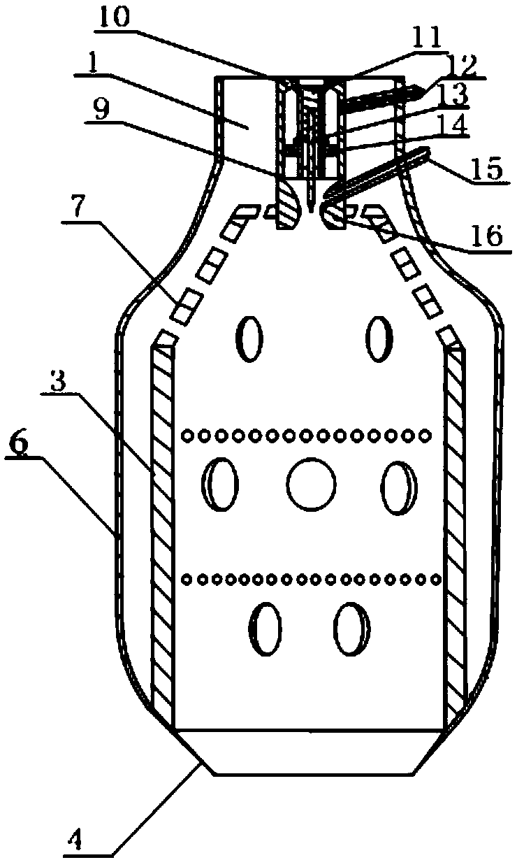
[0040] This embodiment is an aero-engine main combustion chamber based on plasma jet ignition, which is composed of three major parts: a combustion chamber 6 , a flame tube 3 , and a plasma jet igniter 9 . The flame tube 3 is located in the outer casing 6 of the combustion chamber, and the plasma jet igniter 9 is located at the upper end of the flame tube, wherein the jet outlet extends into about a third of the flame tube, and the plasma jet igniter is connected to the combustion chamber through the outer thread. entry port. The outer casing of the combustion chamber, the flame tube and the plasma jet igniter are coaxial.

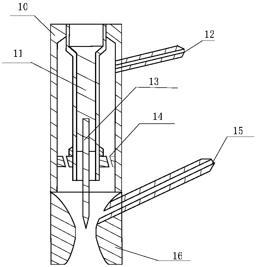
[0041] The plasma jet igniter 9 includes a head 10 , a conductive copper tube 11 , an air inlet 12 , a cathode 13 , a cyclone 14 , a fuel inlet 15 , a jet outlet 16 , an outer tube 17 , and an insulating inner tube 18 . The cathode 13 is located in the conductive copper tube 11, and the cathode 13 and the conductive copper tube 11 are connected by threads...


PUM


Abstract

A main combustion chamber of an aero-engine based on plasma jet ignition and combustion comprises a combustion outer casing, a flame tube and a plasma jet igniter. The flame tube is located in the outer casing of the combustion chamber, and the plasma jet igniter is located at the upper end of the flame tube, wherein the jet outlet extends into about one-third of the flame tube, and the plasma jet igniter is connected to the inlet end of the combustion chamber through an external thread. The outer casing of the combustion chamber, the flame tube and the plasma jet igniter are coaxial. The present invention is based on a very small aero-engine with plasma jet ignition and combustion. And the weight and volume of the combustion chamber, improve the ignition reliability of the aero-engine combustion chamber, and then improve the performance of the aero-engine.

Description

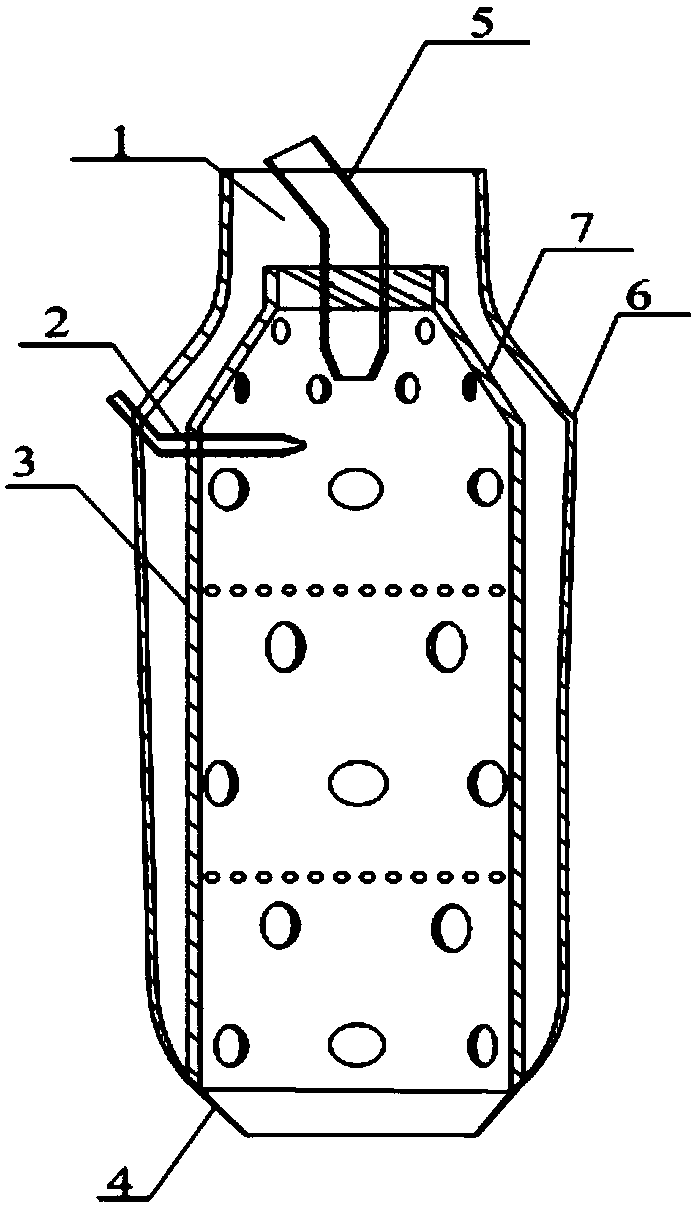
technical field [0001] The invention relates to the field of aero-engines, in particular to a structure of a main combustion chamber of an extremely small aero-engine based on plasma jet ignition and combustion. Background technique [0002] At present, the main combustion chamber of the aviation turbine engine used on the aircraft includes the main combustion chamber air inlet channel 1, the spark plug igniter 2, the flame cylinder 3, the combustion chamber outlet 4, the fuel nozzle 5, the combustion chamber 6 and the flame cylinder diffusion In section 7, the head of the combustion chamber with swirler is basically used, and at the same time, electric spark is used for ignition. The combustion chamber of this ignition method has many shortcomings, and due to the limitation of the principle, there is little room for improvement. Combustion chambers based on swirlers and spark ignition mainly have the following disadvantages: [0003] 1. The swirler at the head of the main ...

Claims


Application Information

Patent Timeline
IPC IPC(8): F02P23/00F02K9/34F02K9/62
CPCF02K9/34F02K9/62F02P23/00
Inventor 于锦禄何立明秦建飞杨迎辉陈鑫金涛彭谦斌唐琦
Owner AIR FORCE UNIV PLA
Learn More