Low-speed axial plunger hydraulic pump

A technology of hydraulic pump and plunger, applied in the field of axial plunger hydraulic pump, can solve the problems of small transmission resistance and friction loss, pulsation of output flow, poor self-priming characteristics, etc., to reduce friction, reduce radial friction and absorb oil. full effect

Active Publication Date: 2017-02-22
李海荣
View PDF10 Cites 7 Cited by
  • Summary
  • Abstract
  • Description
  • Claims
  • Application Information

AI Technical Summary

Problems solved by technology

[0004] In order to solve the problems of existing axial plunger hydraulic pumps such as poor self-priming characteristics, pulsating output flow, large noise, small displacement, and short service life, the present invention provides a low-speed plunger hydraulic pump. It has good self-priming characteristics, low output flow pulsation and noise under low-speed operation environment, and has the characteristics of small transmission resistance and friction, high efficiency, small volume, large displacement and long service life.

Method used


Image

  • Low-speed axial plunger hydraulic pump
  • Low-speed axial plunger hydraulic pump
  • Low-speed axial plunger hydraulic pump

Examples


Embodiment Construction

[0059] Below in conjunction with accompanying drawing and specific embodiment the present invention is described in further detail:

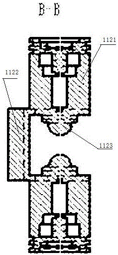
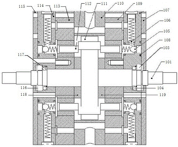
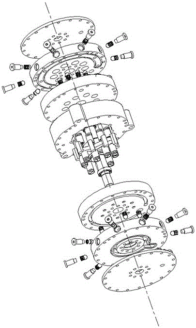
[0060] Such as figure 1 , figure 2 The low-speed axial plunger hydraulic pump shown is mainly composed of a cam drive shaft 101, a cam box 110, left and right plunger cylinders 113 and 112, a two-way conjoined plunger 111, left and right oil distribution plates 114 and 108, and left and right side covers 115 and 107;

[0061] Cam transmission shaft is made up of the integral structure and one-way bearing that drive shaft 101 and double-sided space cam 111 form one-way transmission mechanism, and double-sided space cam 111 has two left-hand helical surfaces and two right-hand helical surfaces (i.e. lift, drop stroke, lift, and drop four-section curved surface), when the cam drive shaft rotates one revolution, the two-way conjoined plunger 112 realizes two working cycles in the plunger cylinder of the plunger cylinder body 113.

[0062] The he...


PUM


Abstract

The invention provides a low-speed axial plunger hydraulic pump. A cam transmission shaft is of an overall structure formed by a transmission shaft and a cam disc. A cam case is mounted on the outer portion of the cam disc in a sleeving manner. Bidirectional joint plungers, plunger cylinder bodies, oil distribution discs and side covers are sequentially mounted on the two sides of the cam case, and the cam transmission shaft is mounted on the left oil distribution disc and the right oil distribution disc in a sleeved manner through bearings. Each bidirectional joint plunger is formed by connecting plunger bodies at the left end and the right end into a whole through a guide sliding block. The plunger bodies at the two ends of each bidirectional joint plunger and plunger cylinders of the left plunger cylinder body and the right plunger cylinder body are mounted in a clearance fit manner. The guide sliding blocks of the bidirectional joint plungers are mounted in an axial guide groove of the cam case in a sleeved manner, and the guide sliding blocks do reciprocating motion in the axial guide sleeve. The low-speed axial plunger hydraulic pump has the beneficial effects that the power input method of the cam transmission shaft is adopted, the cam transmission shaft is of the overall structure formed by the transmission shaft and the dual-face space cam disc, the dual-face space cam disc is provided with two working faces, and when the cam transmission shaft rotates by a circle, the plunger cylinders in the plunger bodies achieve two working cycles.

Description

technical field [0001] The invention relates to the technical field of hydraulic transmission, in particular to an axial plunger hydraulic pump which adopts a double-sided space curved cam disc design and is suitable for low-speed operation. Background technique [0002] The plunger pump is an important device of the hydraulic system. It relies on the reciprocating movement of the plunger in the cylinder to change the volume of the sealed working chamber to realize oil suction and pressure. Piston pumps are generally divided into single plunger pumps, horizontal plunger pumps, axial plunger pumps and radial plunger pumps. An axial piston hydraulic pump is a piston pump in which the reciprocating direction of the piston or plunger is parallel to the central axis of the cylinder. Axial piston hydraulic pumps work by using the volume change caused by the reciprocating movement of the plunger parallel to the transmission shaft in the plunger cylinder. Since both the plunger an...

Claims


Application Information

Patent Timeline
Patent Type & Authority Applications(China)
IPC IPC(8): F04B1/12F04B53/14F04B53/00F04B17/03
CPCF04B1/12F04B1/122F04B1/124F04B1/128F04B17/03
Inventor 李海荣
Owner 李海荣
Why Eureka
Try Eureka