Operation control method, system and air compressor system

An air compressor and operation control technology, applied in the field of rail transit, can solve the problems of short single operation time and emulsification of lubricating oil.

Active Publication Date: 2017-02-22
ZHUZHOU ELECTRIC LOCOMOTIVE CO LTD
View PDF5 Cites 10 Cited by
  • Summary
  • Abstract
  • Description
  • Claims
  • Application Information

AI Technical Summary

Problems solved by technology

[0003] In view of this, the present application provides an operation control method, system and air compressor system, which are used to solve the problem of lubricating oil emulsification caused by the short single operation time of the air compressor system of rail vehicles

Method used


Image

  • Operation control method, system and air compressor system
  • Operation control method, system and air compressor system
  • Operation control method, system and air compressor system

Examples


Embodiment 1

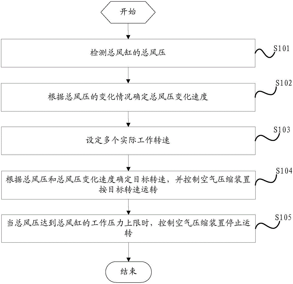
[0062] figure 1 It is a flow chart of steps of an operation control method provided in the embodiment of the present application.

[0063] Such as figure 1 As shown, the operation control method provided in this embodiment is applicable to the air compressor system of a rail vehicle, and the air compressor system includes an air compression device and a main air cylinder. The air compression device generally includes two compressors, namely the first compressor and the second compressor. The air inlet of the main air cylinder is connected with the air outlet of the two compressors for storing compressed air. The operation control method Specifically include the following steps:

[0064] S101: Detect the total air pressure of the main air cylinder.

[0065] The pressure of the main air cylinder is detected by means of a pressure detection device arranged on the main air pipe of the main air cylinder, and the total wind pressure reflecting the pressure of the total air cylind...

Embodiment 2

[0102] Figure 4 It is a structural block diagram of an operation control system provided by another embodiment of the present application.

[0103] Such as Figure 4 As shown, the operation control system provided in this embodiment is used to control the air compressor system of the rail vehicle, and the air compressor system includes an air compression device and a main air cylinder. The air compression device generally includes two compressors, namely the first compressor and the second compressor. The air inlet of the main air cylinder is connected with the air outlet of the two compressors to store compressed air. The operation control system It includes a total wind pressure detection module 10 , a total wind pressure change calculation module 20 , a working speed setting module 30 and an operation control module 40 .

[0104] The total wind pressure detection module 10 is used to detect the total wind pressure of the total wind cylinder.

[0105] Specifically, the p...

Embodiment 3

[0135] This embodiment provides an air compressor system, and the air compressor system is provided with the operation control system provided by the above embodiments. It can avoid emulsification of lubricating oil.


PUM


Abstract

The application discloses an operation control method, system and an air compressor system. The method and the system are used for controlling the air compressor system of track locomotives. The total blast pressure of a total air cylinder is detected; when the total blast pressure changes, the total blast pressure change rate is calculated according to the change conditions of the total blast pressure, wherein the total blast pressure change rate comprises the total blast pressure rising rate and the total blast pressure descending rate; multiple actual operating rotating rates which successively descend are determined according to the maximum operation rotating rate of the air compressing device; a target rotating rate is selected from the multiple actual operating rotating rates according to the total blast pressure and total blast pressure changes and the air comprising device is controlled to operate at the target rotating rate; when the total blast pressure value reaches at the maximum operating pressure of the total air cylinder, the air compressing device is controlled to stop rotating. The technical scheme of the application can solve the problem of emulsification of lubricant due to short single operation time of an air compressor system.

Description

technical field [0001] The present application relates to the technical field of rail transit, and more specifically, relates to an operation control method, system and air compressor system. Background technique [0002] The air compressor is an important power equipment on the rail locomotive, which provides the wind source for the rail locomotive to decelerate and brake by outputting high-pressure gas. In order to ensure the safe operation of rail locomotives, the rated displacement of their air compressors is often designed based on ensuring sufficient air volume under extreme conditions. However, the air volume of rail locomotives in normal operation is very different from extreme conditions, that is, the air compressor only needs to work at a lower working rate to meet the normal needs of rail locomotives. In this case, lubricating oil The temperature often cannot meet the requirements of oil-water separation, and the inhaled water cannot be removed, resulting in the ...

Claims


Application Information

Patent Timeline
Patent Type & Authority Applications(China)
IPC IPC(8): F04B49/20F04B49/02
CPCF04B49/02F04B49/20
Inventor 李希宁郭莹莹黄金虎毛金虎李锦辉谭朝晖张娟
Owner ZHUZHOU ELECTRIC LOCOMOTIVE CO LTD
Why Eureka
Try Eureka