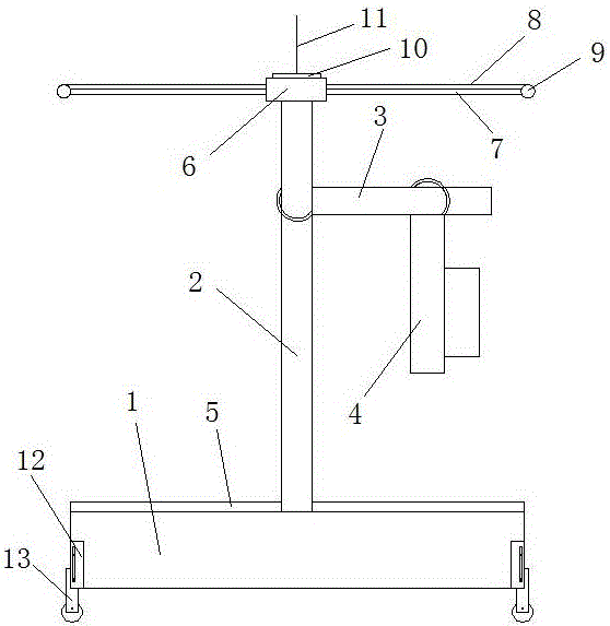
Wireless network receiver holder
A wireless network and receiver technology, applied in the field of wireless network receiver brackets, can solve the problems of inability to adjust height and angle, and no rain protection function
- Summary
- Abstract
- Description
- Claims
- Application Information
AI Technical Summary
Problems solved by technology
Method used
Image
Examples
specific Embodiment 1
[0021] figure 1 Shown is a wireless network receiver bracket, including a base 1, a frame body and a rain-shielding device, the base 1 is arranged along the horizontal direction, the above-mentioned frame body includes a vertical support rod 2, a height adjustment rod 3 and an angle adjustment rod 4, the vertical Vertical to the support rod 2 is set on the base 1, the rain-shielding device is set on the top of the vertical support rod 2; the height adjustment rod 3 is movably arranged on the vertical support rod 2, and the setting direction is parallel to the base 1; the angle adjustment rod 4 activities are set on the height adjustment rod 3, the setting direction is perpendicular to the height adjustment rod 3, and the angle adjustment rod 4 is provided with a wireless network receiver installation part; the upper surface of the above-mentioned base 1 is provided with a solar panel 5, and the inside of the base There is a storage battery, and the solar panel 5 is electricall...
specific Embodiment 2
[0024] This embodiment further illustrates the structure of the rain-shielding device on the basis of specific embodiment 1. The above-mentioned rain-shielding device includes a power box 6, a push rod 7, a transparent plastic film 8 and a film rod 9, and the power box 6 Fixed on the top of the vertical support rod 2, the power box 6 is equipped with a cylinder and a wireless remote control receiving device that can be pushed in both directions at the same time. The wireless remote control node receiving device is connected to the electric signal of the cylinder, and the cylinder is electrically connected to the battery. Parallel to the horizontal direction, the two ends of the cylinder along the pushing direction are respectively connected with push rods 7, and the push rods 7 pass through the box body of the power box 6, and the other end of the push rods 7 connected with the cylinder is connected with a membrane rod parallel to the horizontal plane 9. The setting direction o...
specific Embodiment 3
[0027] This embodiment adds a lightning protection device on the basis of the specific embodiment 1. The top of the power box 6 is connected with a lightning protection device. The lightning protection device includes an insulating pad 10 and a lightning rod 11, and the insulating pad 10 is fixed on the upper surface of the power box 6. Lightning rod 11 is arranged on the insulating spacer 10 along the vertical direction of the upper surface of power box 6, lightning rod 11 and insulating spacer 10 are provided with lightning flat steel, and the other end of lightning flat steel is grounded. A lightning protection device is arranged on the top of the power box 6, which can prevent lightning strikes from causing damage to the power box 6 and the wireless network receiver during thunderstorms. The insulating pad 10 can effectively prevent the electric energy from being transmitted to the power box 6 and the wireless network receiver during lightning strikes. On the other hand, th...
PUM
 Abstract
Description
Claims
Application Information
 - R&D
- Intellectual Property
- Life Sciences
- Materials
- Tech Scout
- Unparalleled Data Quality
- Higher Quality Content
- 60% Fewer Hallucinations
Browse by: Latest US Patents, China's latest patents, Technical Efficacy Thesaurus, Application Domain, Technology Topic, Popular Technical Reports.
© 2025 PatSnap. All rights reserved.Legal|Privacy policy|Modern Slavery Act Transparency Statement|Sitemap|About US| Contact US: help@patsnap.com

