Efficient air conditioning unit with multiple refrigerant loops

A technology for refrigerant circuits and air-conditioning units, applied in refrigerators, refrigeration components, refrigeration and liquefaction, etc., can solve the problems of limiting the energy efficiency of air-conditioning units, uneven heat transfer temperature difference, waste of heat exchange area, etc., and achieves significant energy-saving effects. The effect of improving the energy efficiency of the unit and improving the energy efficiency

Inactive Publication Date: 2017-02-22
TONGJI UNIV
View PDF5 Cites 10 Cited by
  • Summary
  • Abstract
  • Description
  • Claims
  • Application Information

AI Technical Summary

Problems solved by technology

[0005] The temperature difference heat transfer loss is due to the significant temperature change of the air passing through the heat exchanger, but the phase change temperature and pressure-related refrigerant are difficult to coordinate with the air temperature change
This mismatched temperature change causes a large local temperature difference, resulting in a huge loss; the local temperature difference is too small, that is, there is a "temperature pinch", which wastes the heat transfer area
Therefore, uneven heat transfer temperature difference is one of the important reasons that limit the energy efficiency of air conditioning units
[0006] But currently no air conditioning unit uses this principle to improve performance

Method used


Image

  • Efficient air conditioning unit with multiple refrigerant loops
  • Efficient air conditioning unit with multiple refrigerant loops
  • Efficient air conditioning unit with multiple refrigerant loops

Examples


Embodiment 1

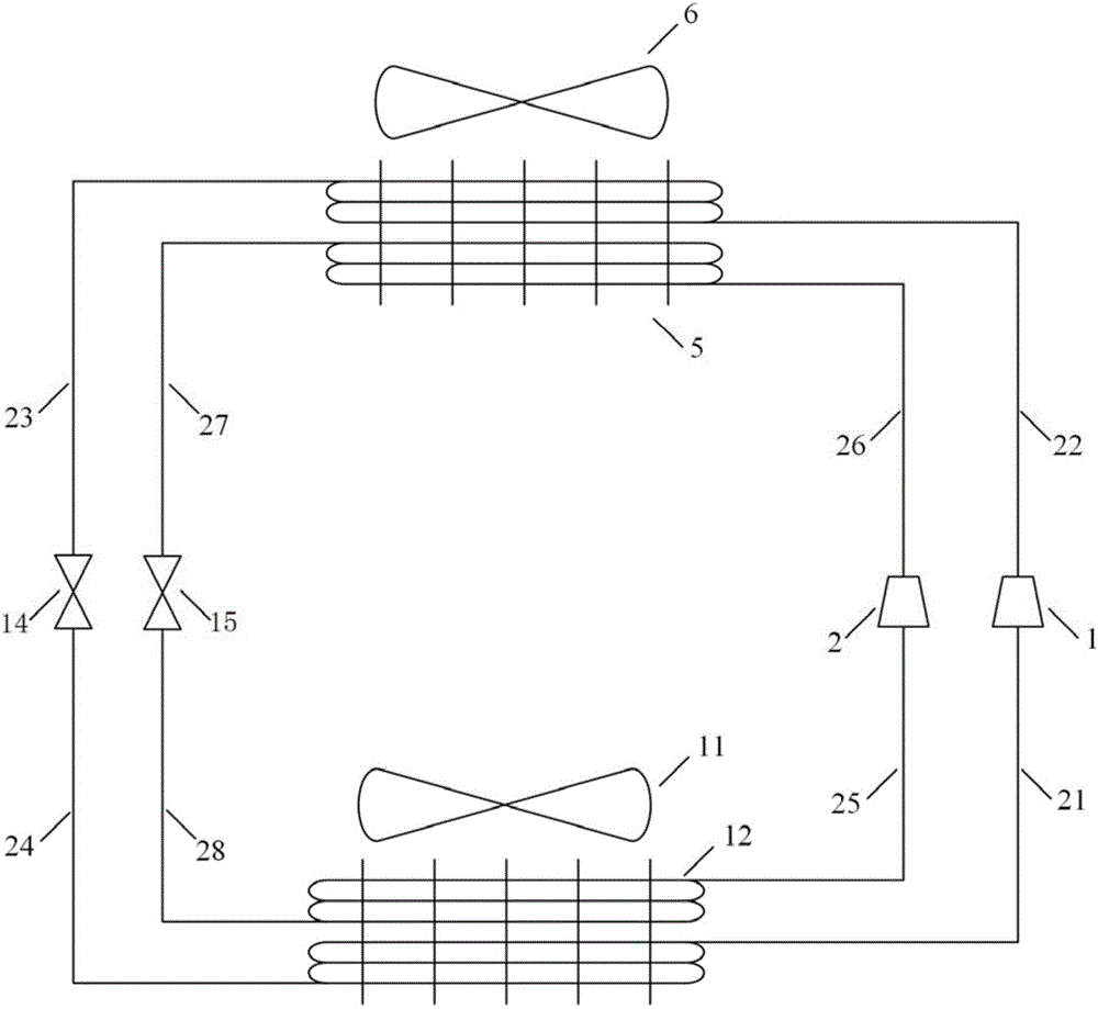
[0051] High-efficiency air conditioning units with dual refrigerant circuits such as figure 1 As shown, it includes an outdoor heat exchanger 5 with dual refrigerant flow paths, an indoor heat exchanger 12 with dual refrigerant flow paths, a first cycle compressor 1, a second cycle compressor 2, a first cycle throttling device 14, and a second cycle throttling device 14. Circulation throttling device 15, external fan 6 and blower fan 11.

[0052] The dual refrigerant flow path outdoor heat exchanger 5 has a high-temperature refrigerant channel, a low-temperature refrigerant channel, and an air channel. The two refrigerant channels are arranged forward and backward along the direction of the air channel. The low-temperature refrigerant channel is near the windward side, and the high-temperature refrigerant channel Setting near the wind outlet;

[0053] The double refrigerant flow path indoor heat exchanger 12 has a high temperature refrigerant channel, a low temperature refrig...

Embodiment 2

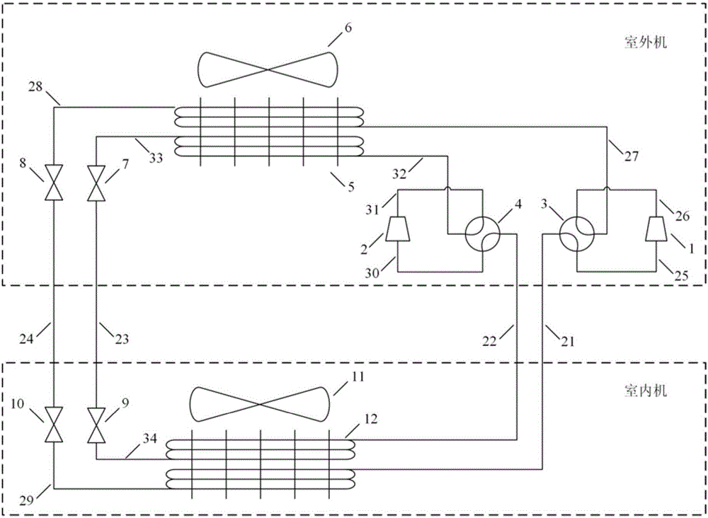
[0070] Such as figure 2 As shown, the difference between this embodiment and embodiment 1 is:

[0071] In this embodiment, the high-efficiency air-conditioning unit with dual refrigerant circuits also includes a four-way reversing valve 3 for the first cycle and a four-way reversing valve 4 for the second cycle, and a four-way reversing valve 3 for the first cycle and a four-way reversing valve for the first cycle The compressor 1 is connected, and the first cycle four-way reversing valve 3 is used to regulate the flow direction of the refrigerant in the first cycle, the second cycle four-way reversing valve 4 is connected with the second cycle compressor 2, and the second cycle four-way The one-way reversing valve 4 is used to regulate the flow direction of the refrigerant in the second cycle, and then, the cooling and heating working conditions are switched by controlling the four-way reversing valve 3 of the first cycle and the four-way reversing valve 4 of the second cycl...

Embodiment 3

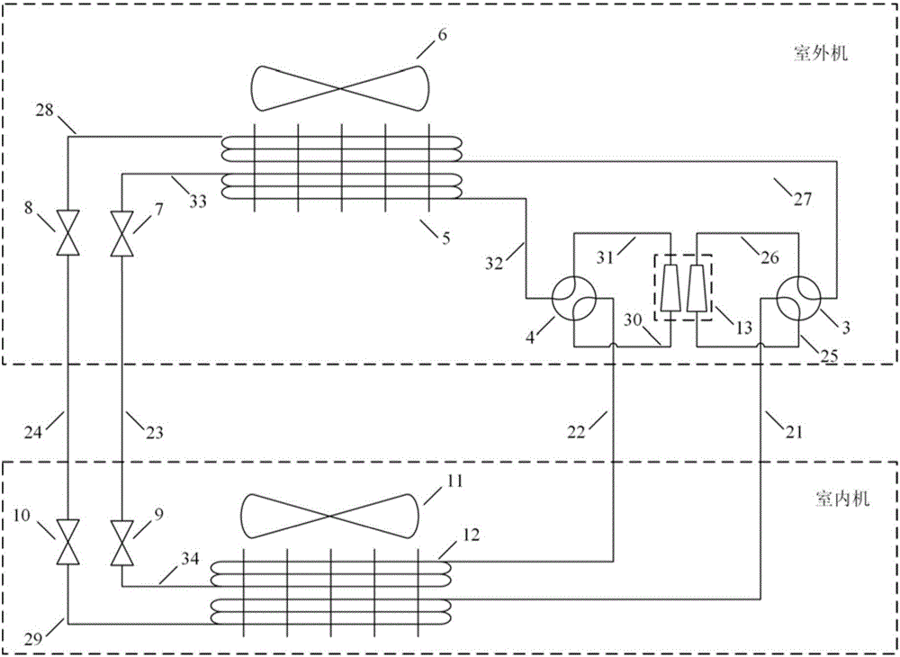
[0083] Such as image 3 As shown, the differences between this embodiment and embodiment 2 are:

[0084] In this embodiment, the first cycle compressor 1 and the second cycle compressor 2 are replaced by a double-cylinder double-suction and exhaust pressure compressor 13, and the double-cylinder double-suction and exhaust pressure compressor 13 has two Cylinder, the two cylinders have different suction pressure and exhaust pressure respectively, the cylinder connected with the first cycle is the first cycle cylinder, and the cylinder connected with the second cycle is the second cycle cylinder, the double suction and exhaust pressure of the double cylinder The compressor 13 can be a vapor compression refrigerator or a heat pump compressor.

[0085] Compared with Embodiment 2, the first circulation compressor 1 and the second circulation compressor 2 are replaced by a double-cylinder double-suction and exhaust pressure compressor 13 to simplify the system structure.


PUM


Abstract

The invention relates to an efficient air conditioning unit with multiple refrigerant loops. The efficient air conditioning unit comprises an outdoor heat exchanger with multiple refrigerant flow paths, an indoor heat exchanger with multiple refrigerant flow paths, a plurality of compressors and a plurality of refrigerant circulating throttling devices, wherein the outdoor heat exchanger with the multiple refrigerant flow paths is equipped with a plurality of refrigerant channels; the indoor heat exchanger with the multiple refrigerant flow paths is equipped with a plurality of refrigerant channels; and one refrigerant channel of the outdoor heat exchanger with multiple refrigerant flow paths, one compressor, one refrigerant channel of the indoor heat exchanger with multiple refrigerant flow paths, and one circulating throttling device separately communicate to form a plurality of refrigerant circulating loops. Compared with the prior art, the efficient air conditioning unit has the advantages that by increasing quantity of refrigerant loops in the air conditioning unit, a plurality of condensing temperatures and evaporating temperatures, which have certain temperature gradient, are created, non-uniformity of heat exchange temperature difference is improved, and efficiency of a steam compression air conditioning unit is improved.

Description

technical field [0001] The invention relates to a vapor compression refrigeration / heat pump air conditioner unit, in particular to a high-efficiency air conditioner unit with multiple refrigerant circuits. Background technique [0002] With the continuous improvement of living standards, the power consumption of air conditioners continues to rise rapidly, and currently accounts for more than 40% of building energy consumption. Air conditioning units based on the vapor compression cycle are the most widely used at present. [0003] The main structure of the vapor compression air conditioning unit includes a compressor, a condenser, an evaporator, and a throttling device. Its working process is: the low-temperature and low-pressure liquid refrigerant first absorbs heat from the low-temperature heat source in the evaporator and is vaporized into low-pressure steam. Then the refrigerant gas is completely compressed into high temperature and high pressure vapor in the compresso...

Claims


Application Information

Patent Timeline
Patent Type & Authority Applications(China)
IPC IPC(8): F25B1/00F25B31/00F25B41/06F25B41/30F25B41/31F25B41/34F25B41/37
CPCF25B1/00F25B31/00F25B41/30
Inventor 曹祥张子杨张春路
Owner TONGJI UNIV
Why Eureka
Try Eureka