Efficient drying device for biofuels

A biofuel and drying device technology, applied in the drying, drying, dryer and other directions of granular materials, can solve the problems of slow drying speed, low drying efficiency, air and air pollution, etc. Guaranteed drying effect and improved dispersion effect

Inactive Publication Date: 2017-02-22
ZHENGZHOU RENHONG PHARMA CO LTD
View PDF0 Cites 12 Cited by
  • Summary
  • Abstract
  • Description
  • Claims
  • Application Information

AI Technical Summary

Problems solved by technology

[0002] In recent years, due to the use of biogas, natural gas and coal, straw is no longer the main fuel used in rural areas, and a large amount of straw is directly ignited on the ground by people, causing air and atmospheric pollution, and at the same time causing a decline in biomass energy. a lot of waste
[0003] In order to solve the above-mentioned waste of biomass fuels, devices and equipment that make biomass fuels such as straw, straw, and sawdust into pellets and use biomass pellets as fuel for production and living have appeared on the market
[0004] At present, there are many biomass fuels available in the market, mainly including: straw, straw, sawdust and other agricultural and forestry wastes. These fuels have a common feature of high moisture content, which will directly affect the effective utilization of biomass fuels.
There are a lot of equipment for drying biomass fuel in the prior art, but there are certain shortcomings and deficiencies, such as low drying efficiency, unreasonable structural design, slow drying speed, and the drying effect cannot meet the requirements, etc.

Method used


Image

  • Efficient drying device for biofuels
  • Efficient drying device for biofuels

Examples


Embodiment Construction

[0017] The following will clearly and completely describe the technical solutions in the embodiments of the present invention with reference to the accompanying drawings in the embodiments of the present invention. Obviously, the described embodiments are only some, not all, embodiments of the present invention. Based on the embodiments of the present invention, all other embodiments obtained by persons of ordinary skill in the art without making creative efforts belong to the protection scope of the present invention.

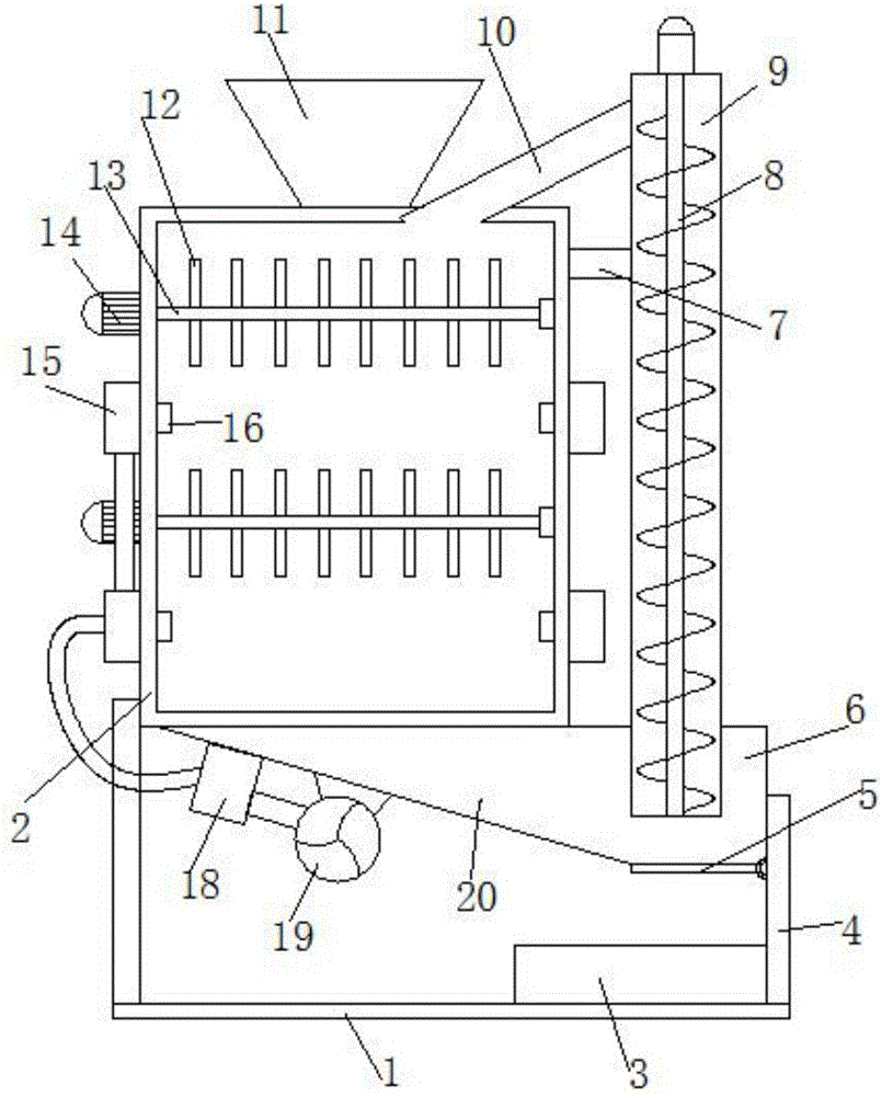
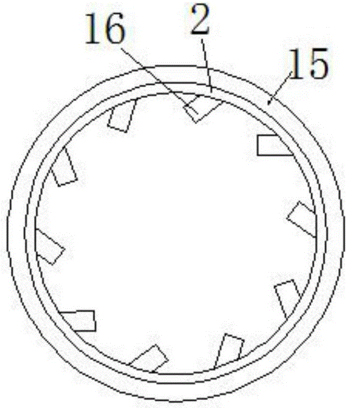
[0018] see Figure 1-2 , in an embodiment of the present invention, a high-efficiency drying device for biofuels includes a base 1 and a drying box 2, a drying box 2 is arranged above the base 1, and the drying box 2 has a cylindrical body, which is dried The lower end of the case 2 is provided with a collection box 6, the left side of the collection box 6 is a material guide slope 20, and the upper surface of the material guide slope 20 is provided with a cer...


PUM


Abstract

The invention discloses an efficient drying device for biofuels. The efficient drying device comprises a base and a drying box, wherein the drying box is arranged above the base; the drying box is a cylindrical barrel; a collection box is arranged at the lower end of the drying box; the left side surface of the collection box is a guide oblique surface; supporting legs are arranged among the drying box, the collection box and the base; a discharge baffle plate is arranged at the bottom of the collection box; a lifting barrel is embedded on the upper end face of the collection box where the discharge baffle plate is positioned; a fixed rod is arranged between the left upper side of the lifting barrel and the drying box; a screw conveyer is arranged inside the lifting barrel; a material return pipeline is arranged between the left upper side of the lifting barrel and the top of the drying box; a feeding pipe is arranged on the upper end face of the lifting barrel; a feed hopper is arranged in the middle position of the top of the drying box; stirring shafts are horizontally arranged inside the drying box under the feed hopper; a plurality of stirring rods are arranged on the stirring shafts; and the left ends of the stirring shafts penetrate through the left side wall of the drying box, and are connected with driving motors. According to the efficient drying device, the structure is simple and reasonable, circular drying of materials is achieved, the drying effect is good, and the practicability is high.

Description

technical field [0001] The invention relates to the technical field of biomass fuels, in particular to a high-efficiency drying device for biomass fuels. Background technique [0002] In recent years, due to the use of biogas, natural gas and coal, straw is no longer the main fuel used in rural areas, and a large amount of straw is directly ignited on the ground by people, causing air and atmospheric pollution, and at the same time causing a decline in biomass energy. A lot of waste. [0003] In order to solve the above-mentioned waste of biomass fuels, devices and equipment that make biomass fuels such as straw, straw, and sawdust into pellets and use biomass pellets as fuel for production and living have appeared on the market. [0004] At present, there are many biomass fuels available in the market, mainly including: straw, straw, sawdust and other agricultural and forestry wastes. These fuels have a common feature of high moisture content, which will directly affect th...

Claims


Application Information

Patent Timeline
Patent Type & Authority Applications(China)
IPC IPC(8): F26B11/16F26B21/00F26B25/04F26B25/00
CPCF26B11/16F26B21/001F26B21/004F26B25/002F26B25/04F26B2200/08
Inventor 郜佩环
Owner ZHENGZHOU RENHONG PHARMA CO LTD
Why Eureka
Try Eureka