Detection circuit, preamplifier and eddy current sensor

A detection circuit and front-end device technology, which is applied in the direction of using electrical devices, instruments, and measuring devices, can solve problems such as temperature drift, measurement accuracy decline, and detection circuits that are easily affected by temperature, so as to improve output accuracy and improve The ability to resist temperature changes and reduce the effect of temperature on the signal

Active Publication Date: 2019-07-09
GREE ELECTRIC APPLIANCES INC +1
View PDF9 Cites 0 Cited by
  • Summary
  • Abstract
  • Description
  • Claims
  • Application Information

AI Technical Summary

Problems solved by technology

Therefore, the defect in the prior art is that the detection circuit is easily affected by temperature, resulting in temperature drift, resulting in a decrease in measurement accuracy

Method used


Image

  • Detection circuit, preamplifier and eddy current sensor
  • Detection circuit, preamplifier and eddy current sensor
  • Detection circuit, preamplifier and eddy current sensor

Examples


Embodiment 1

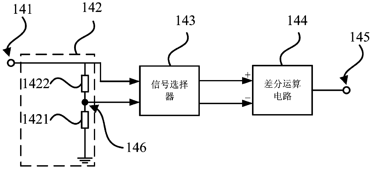
[0035] In order to solve the problem that the detection circuit in the prior art is easily affected by temperature, the embodiment of the present invention provides a detection circuit, please refer to figure 2 , which is a schematic diagram of a detection circuit provided in Embodiment 1 of the present invention.

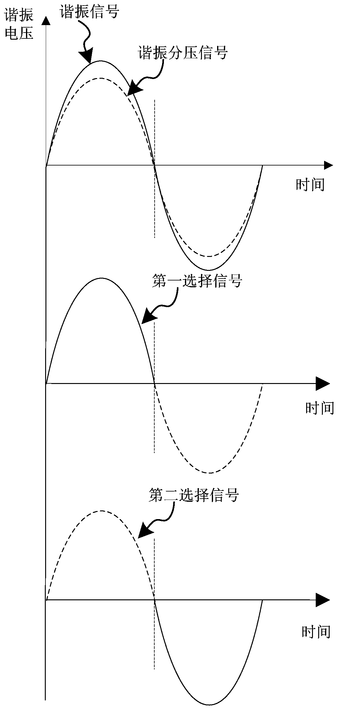
[0036] This embodiment provides a detection circuit 14, including: an input terminal 141, used to receive the input resonance signal; a voltage divider circuit 142, connected to the input terminal 141, and a lead terminal 146 is set in the voltage divider circuit 142, which is used to adjust the resonance signal. After the signal is divided, the resonance voltage division signal is output; the signal selector 143 is connected to the input terminal 141 and the lead end 146 respectively, and is used to obtain the resonance signal and the resonance voltage division signal, and is used to divide the first half cycle signal of the resonance signal and the resonance volt...

Embodiment 2

[0046] This embodiment provides a front end, please refer to Figure 5 , which is a schematic diagram of a front-end device provided in Embodiment 2 of the present invention.

[0047] A pre-amplifier 1, including the detection circuit 14 provided by any embodiment of the present invention, also includes: an excitation source circuit 11, used to generate an excitation source signal; a voltage dividing resistor 12, connected in series with the excitation source circuit 11 and LC parallel resonance Between the circuits 13, it is used to divide the excitation source signal; the LC parallel resonant circuit 13 is connected with the voltage dividing resistor 12 and the detection circuit 14, and is used to receive the divided excitation source signal, and output the resonance signal to the detection circuit 14 ; The filter circuit 15 is connected to the detection circuit 14, receives the output signal of the detection circuit 14, and outputs the signal after filtering.

[0048] Spec...

Embodiment 3

[0053] This embodiment provides an eddy current sensor, please refer to Image 6 , which is a schematic diagram of an eddy current sensor provided in Embodiment 3 of the present invention.

[0054] An eddy current sensor includes the above-mentioned front-end device 1, and also includes a probe 3 and a cable 2, and the probe 3 is connected to the front-end device 1 through the cable 2.

[0055] In this technical solution, since the front-end device improves the ability to resist temperature changes, the signal processing and output of the front-end device are less affected by the temperature, so the eddy current sensor is also less affected by the temperature, which improves the eddy current The measurement accuracy of the sensor.


PUM


Abstract

The embodiment of the invention proposes a detection circuit, a preposed device, and an electrical vortex sensor. The detection circuit comprises an input end which is used for receiving an inputted resonant signal; a voltage-dividing circuit which is connected with the input end, is provided with a leading-out end, and is used for outputting a resonant voltage-dividing signal after the voltage dividing of the resonant signal; a signal selector which is connected with the input end and the leading-out end, and is used for obtaining the resonance signal and the resonant voltage-dividing signal, and outputting a first selection signal and a second selection signal; a differential operation circuit which comprises a positive phase input end, an inverted input end and an output end, wherein the positive phase input end is used for receiving the first selection signal, the inverted input end is used for receiving the second selection signal, and the differential operation circuit is used for carrying out the differential operation of the first and second selection signals, and a detection signal obtained through operation is outputted from the output end. The detection circuit effectively reduces the impact from the temperature, and improves the output precision of the preposed device and the measurement precision of the electrical vortex sensor.

Description

technical field [0001] The embodiment of the present invention relates to the electrical technology of distance measuring equipment, in particular to a detection circuit, a front end device and an eddy current sensor. Background technique [0002] With the improvement of processing accuracy, there are more and more demands for the measurement of small displacements in industrial systems, especially for high-precision processing equipment, which generally require a resolution on the order of microns. This puts forward higher and higher precision requirements for displacement sensors, and eddy current sensors have been used more and more in industrial sites because of their excellent characteristics. [0003] Traditional eddy current sensor systems generally use half-wave detection, figure 1 It is a schematic diagram of a commonly used half-wave detection circuit. The half-wave detection circuit is a common circuit that uses the unidirectional conduction characteristic of a ...

Claims


Application Information

Patent Timeline
Patent Type & Authority Patents(China)
IPC IPC(8): G01B7/02G01D3/032
CPCG01B7/02G01D3/032
Inventor 贺永玲薛贺杰汪波
Owner GREE ELECTRIC APPLIANCES INC
Why Eureka
Try Eureka