Detection method for identifying surface quality of continuous laser seam of metal workpiece online

A technology of weld surface and detection method, which is applied in the direction of optical testing for flaws/defects, etc., can solve problems such as measurement failure, safety hazards, and inability to meet large-scale automated welding production, and achieve the effect of simple equipment

Active Publication Date: 2017-02-22
龚新林 +5
View PDF6 Cites 21 Cited by
  • Summary
  • Abstract
  • Description
  • Claims
  • Application Information

AI Technical Summary

Problems solved by technology

This method only relies on the weld height information, and there are fewer types of weld defects that can be identified, and the surface of the weld is usually rough, and disturbances such as scum, spatter, and dust on the surface seriously affect the accuracy of height measurement
In addition, the line scanning method is time-consuming and has limitations in the field of continuous long weld detection
[0006] 3) The paper "Structured Light Visual Inspection of Weld Defects in Laser Welding of Unequal Thick Plates" ("Laser Technology" Vol. 35 No. 4, 2011) uses the structured light active visual inspection method to calculate the height information of the weld surface, but the The method can only obtain the concavity or convexity state of the weld, and cannot detect the surface defects of the weld and the location of the weld
[0007] 4) The paper "Weld Surface Defect Detection System Based on Line Laser Scanning" ("Welding" 2016 No. 2) uses line laser to scan the weld surface, and uses the method of single contour fitting and multi-contour combination to judge the weld surface defects, but this method can only be applied to arc welding seams with larger widths, and is not suitable for narrow and thin welds...

Method used


Image

  • Detection method for identifying surface quality of continuous laser seam of metal workpiece online
  • Detection method for identifying surface quality of continuous laser seam of metal workpiece online
  • Detection method for identifying surface quality of continuous laser seam of metal workpiece online

Examples


Embodiment Construction

[0095] The technical solutions in the embodiments of the present invention will be clearly and completely described below in conjunction with the accompanying drawings in the embodiments of the present invention. Obviously, the described embodiments are only a part of the embodiments of the present invention, rather than all the embodiments. Based on the embodiments of the present invention, all other embodiments obtained by those of ordinary skill in the art without creative work shall fall within the protection scope of the present invention.

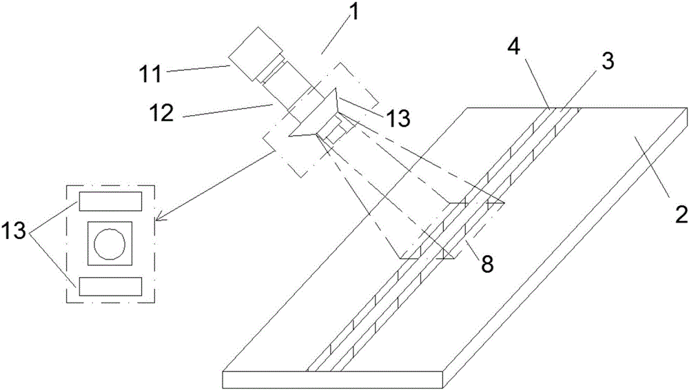
[0096] In a specific embodiment, a detection method for online recognition of the surface quality of a continuous laser weld of a metal workpiece includes the following steps:

[0097] S1: Select a standard laser welding workpiece, take a picture through the camera system, and obtain a complete weld surface image as a series of standard images;

[0098] S2: Take pictures of the weld surface of the workpiece to be inspected through the camera...


PUM


Abstract

The invention provides a detection method for identifying the surface quality of a continuous laser seam of a metal workpiece online, wherein the method comprises the following steps: using a high resolution color area array camera, a high magnification micro lens and double LED illuminating systems to acquire an image of the surface of the seam; afterwards, when dividing a seam region and calculating the characteristic value, translating or rotating the workpiece to shoot an image for other positions of the seam, continuously shooting the image of the seam and completing real-time calculation until reaching a seam welding end or an overlapping point; finally integrating the calculation results of the images, and completing online judgement on the size, the position and the surface defect of the continuous seam. The method is used to complete online detection of the quality of a laser straight welded joint, a curve welding seam or a space welding seam of various ferrous metals and nonferrous metals, and belongs to the category of non-contact visual inspection; a device is simple and compact, high in response speed and strong in anti-jamming capability, has the characteristics of stability, reliability and convenience, and can be widely applied to the field of laser welding of metal materials.

Description

Technical field [0001] The invention relates to the technical field of laser welding, in particular to a detection method for on-line identifying the surface quality of a continuous laser welding seam of a metal workpiece. Background technique [0002] Laser welding technology has been widely used in the connection of metal parts, especially for thin plates with a thickness of less than 3mm. Laser welding has the advantages of small deformation, high degree of automation, and narrow welding heat affected zone. However, in mass welding production, the process stability control of laser welding and the online quality monitoring of laser welding seams have always been key factors in determining product quality. Fluctuations of factors such as beam quality, assembly gap, and surface condition of the workpiece will interfere with the welding process, resulting in weld deviation, holes, weld penetration and other weld defects. Because the laser beam has high energy density and is invi...

Claims


Application Information

Patent Timeline
IPC IPC(8): G01N21/88G01N21/95
Inventor 龚新林杨震华袁振华傅琦俊朱文杰马华强
Owner 龚新林
Why Eureka
Try Eureka