
Waveguide device and three-dimensional display device

A waveguide device and waveguide technology, applied in light guides, instruments, optical components, etc., can solve problems such as poor image quality, reduced image information, light crosstalk, etc., and achieve the effect of increasing the cost of production and increasing the amount of displayed information

Inactive Publication Date: 2017-02-22
SVG TECH GRP CO LTD +1
View PDF10 Cites 47 Cited by
  • Summary
  • Abstract
  • Description
  • Claims
  • Application Information

AI Technical Summary

Problems solved by technology

Chinese patent CN201410187534.X proposes a naked-eye 3D backlight module, which uses one or more groups of LED sequential light sources combined with convex lenses, polygonal prisms, and parallax barriers to achieve multi-view 3D display. It is difficult to realize on the surface, and it is easy to generate crosstalk of light. Therefore, based on the proposed directional backlight solution, no samples or products of actual glasses-free 3D display devices have been seen.
Chinese patent application CN201410852242.3 discloses a scheme for realizing dynamic three-dimensional display by using a multi-layer directional light guide structure composed of nano-pixel gratings, which can realize naked-eye 3D display with large angle and full parallax. However, its display resolution and The number of viewing angles is inversely proportional, that is, the more the number of viewing angles, the lower the display resolution and the worse the image quality
However, the same problem that this solution does not solve is that any time the viewing angle increases, the amount of image information of a single viewing angle decreases, resulting in poor 3D experience

Method used


Image

  • Waveguide device and three-dimensional display device
  • Waveguide device and three-dimensional display device
  • Waveguide device and three-dimensional display device

Examples


Embodiment Construction

[0051] The following will clearly and completely describe the technical solutions in the embodiments of the present invention with reference to the accompanying drawings in the embodiments of the present invention. Obviously, the described embodiments are only some, not all, embodiments of the present invention. Based on the embodiments of the present invention, all other embodiments obtained by persons of ordinary skill in the art without creative efforts fall within the protection scope of the present invention.

[0052] A waveguide device, comprising at least one waveguide device unit, each waveguide device unit includes a waveguide body, the waveguide body is a slab waveguide or a strip waveguide or a curved waveguide with a rectangular cross section, the upper surface and the lower surface of the waveguide body One side of the surface is the light-emitting surface, and the other side is the reflecting surface. Groups of nano-gratings are arranged on the surface of the ligh...


PUM


Abstract

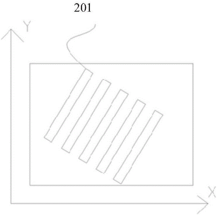
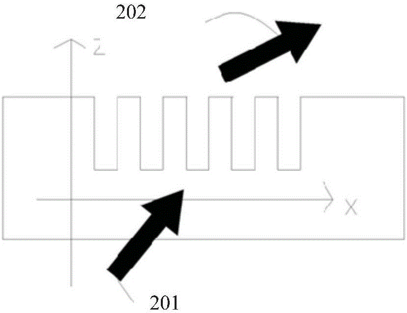
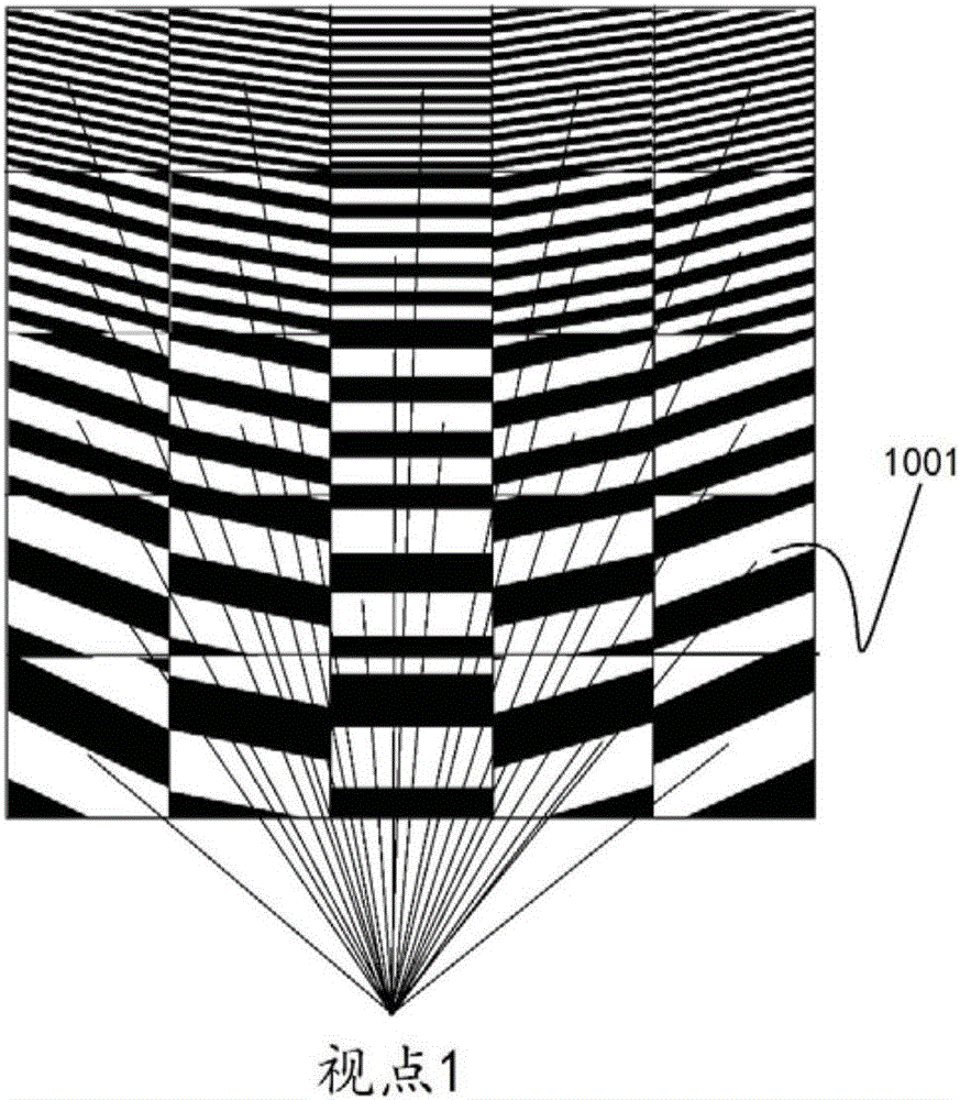
The invention discloses a waveguide device. The waveguide device comprises at least one waveguide device unit, wherein each waveguide device unit comprises a waveguide body; each waveguide body is a slab waveguide, or a strip waveguide or a curved surface waveguide with rectangular cross section; the upper surface of the waveguide body is a light emergent surface, nano gratings in groups are arranged on the surface of the light emergent surface and inside the waveguide body, the nano gratings have convergence effect on lights, and the lights after total reflection of the waveguide body converge in space above the light emergent surface to form at least one viewpoint. By adopting the technical scheme of the invention, a multilayer (two layers and more than two layers) compound type directive light guide plate overlaid by multiple waveguide device units can be constructed, further a way of controlling successive illumination of the layers through frequency division is adopted, display information amount is increased by adopting a method of increasing display frequency, the increased display information amount can be used for multi-view parallax three-dimensional display, also can be used for multifocal multi-field-depth depth three-dimensional display and also can be applied to the multi-view multifocal mixed true three-dimensional display field, and then a naked eye 3D display device is constructed.

Description

technical field [0001] The invention belongs to the field of three-dimensional image display, and in particular relates to a waveguide device and a three-dimensional display device. Background technique [0002] A hologram is an image carrying amplitude and phase information, which can truly reproduce three-dimensional information without causing visual fatigue, and the three-dimensional effect has nothing to do with the distance of the observer. The principle of holographic display can be summarized as follows: a hologram can reproduce a three-dimensional virtual image or a three-dimensional real image in space, each point on the hologram transmits information to all directions in space, and each observation point in space can see the entire image. In other words, the image information propagates through the light field and converges to the observation point. Therefore, at different observation points in space, you can see the entire image from different perspectives witho...

Claims


Application Information

Patent Timeline
IPC IPC(8): G02B6/00G02B27/22G02B30/33
CPCG02B6/005G02B30/33
Inventor 乔文黄文彬朱鸣陈林森方宗豹万文强
Owner SVG TECH GRP CO LTD
Learn More