
Time measuring circuit, method and measuring device

A time measurement and circuit technology, applied in the electronic field, can solve problems such as inaccurate measurement time of access signals, increased D flip-flop setup time, and TDC circuit failure.

Inactive Publication Date: 2019-03-08
SHENZHEN UNIV
View PDF5 Cites 0 Cited by
  • Summary
  • Abstract
  • Description
  • Claims
  • Application Information

AI Technical Summary

Problems solved by technology

[0004] The present invention provides a time measuring circuit, method and measuring equipment, aiming to solve the problem that if the TDC circuit works under the sub-threshold condition of low voltage, it will increase the settling time of the D flip-flop in the traditional TDC circuit, and at the same time improve the minimum time delay chain The delay value will cause inaccurate measurement time of the access signal and affect the measurement range of the time delay chain, resulting in the problem that the TDC circuit cannot work normally

Method used


Image

  • Time measuring circuit, method and measuring device
  • Time measuring circuit, method and measuring device
  • Time measuring circuit, method and measuring device

Examples


Embodiment Construction

[0023] In order to make the purpose, features and advantages of the present invention more obvious and understandable, the technical solutions in the embodiments of the present invention will be clearly and completely described below in conjunction with the accompanying drawings in the embodiments of the present invention. Obviously, the described The embodiments are only some of the embodiments of the present invention, but not all of them. Based on the embodiments of the present invention, all other embodiments obtained by those skilled in the art without making creative efforts belong to the protection scope of the present invention.

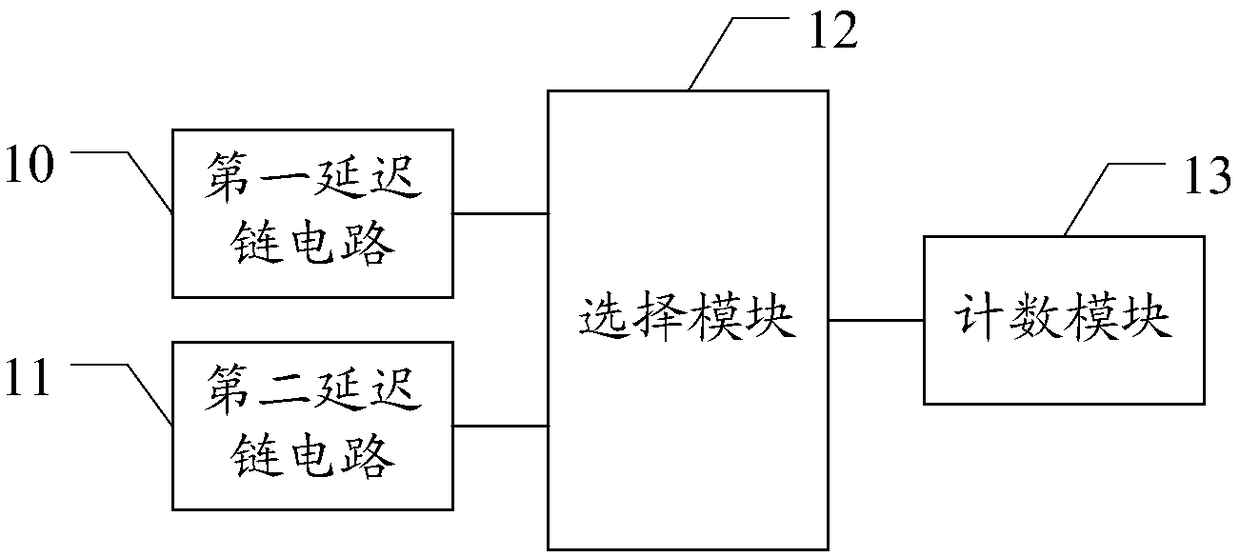
[0024] see figure 1 , figure 1 A schematic structural diagram of the time measurement circuit is provided for the first embodiment of the present invention, which mainly includes the following parts:

[0025] The first delay chain circuit 10 , the second delay chain circuit 11 , the selection module 12 and the counting module 13 .

[0026]...


PUM


Abstract

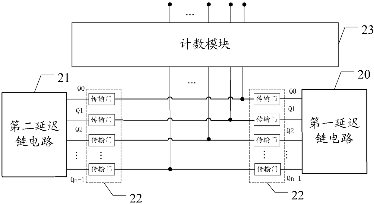
The invention discloses a time measurement circuit and method and measuring equipment. The circuit comprises a first delay chain circuit, a second delay chain circuit, a selection module and a counting module, wherein the selection module conducts connection with the second delay chain circuit if the first received digital signals or the second received digital signals are 0, and the selection module conducts connection with the first delay chain circuit if the first of the received first or second digital signals is 1; and the counter selects a counting manner according to the conducted connection between the selection module and the delay chain circuits, and counts the first or second digital signals according to the counting manner so as to output the counting result. According to the two-section type circuit structure, the accuracy of measuring time of access signals and the circuit measurement range are not influenced, the aim of normal operation under the condition of a low-voltage sub-threshold value is achieved, and the power consumption of the circuit is reduced.

Description

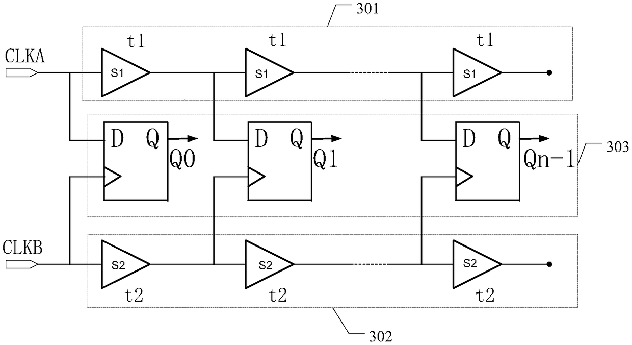
technical field [0001] The invention belongs to the field of electronic technology, and in particular relates to a time measuring circuit, method and measuring equipment. Background technique [0002] Time-to-digital converter (TDC, Time-to-digital converter) is a circuit module for measuring the time range, which is widely used in pulse laser radar, analog-to-digital converters (ADC, Analog-to-digital converters) and phase-locked loop (PLL , phase locked loop) and other circuits. [0003] In the prior art, the TDC circuit is generally connected to the register by a time delay chain, and the measured time is converted into a digital expression through the output of the register, such as figure 1 shown. The structure of the traditional TDC circuit is relatively complete, and it is difficult to reduce power consumption by changing the structure. If the purpose of low-power circuit design is to set the operating voltage of the TDC circuit at a low-voltage sub-threshold, it w...

Claims


Application Information

Patent Timeline
Patent Type & Authority Patents(China)
IPC IPC(8): G04F10/00
CPCG04F10/005
Inventor 姜梅何彦哲孙凯
Owner SHENZHEN UNIV
Learn More