Eureka AIR delivers breakthrough ideas for toughest innovation challenges, trusted by R&D personnel around the world.

Current pulse-typed constant current source with ultrahigh speed

A pulsed, constant current source technology, applied in the field of power supply, can solve the problems of slow rising edge of pulse and low output current of pulse constant current source, and achieve the effect of stable function and simple structure

Inactive Publication Date: 2017-02-22
FUDAN UNIV
View PDF5 Cites 7 Cited by
  • Summary
  • Abstract
  • Description
  • Claims
  • Application Information

AI Technical Summary

Problems solved by technology

[0004] The purpose of the present invention is to provide an optimized and improved pulse constant current source to overcome the problems of low output current and slow pulse rising edge of the pulse constant current source, and to better make the load work in a stable, continuously adjustable constant current source. flow pulse case

Method used


Image

  • Current pulse-typed constant current source with ultrahigh speed

Examples


Embodiment Construction

[0015] The present invention will be described in further detail below in conjunction with the examples, but the protection scope of the present invention is not limited thereto.

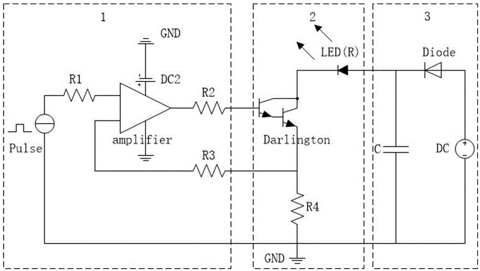
[0016] Such as figure 1 As shown, the overall structure of the present invention is composed of three parts: a constant current source control circuit 1, which outputs a control voltage; a load constant current circuit 2, which outputs a constant current pulse of a corresponding multiple of the control voltage; a capacitor charging and discharging circuit 3, which uses capacitor charging and discharging to make The rising edge of the constant current pulse is faster.

[0017] The concrete structure of the present invention is: constant current source control circuit 1, mainly by power operation amplifier OPA547, resistance R1, R2, R3, power supply DC2 and pulse signal source constitute; Load constant current circuit 2, mainly by Darlington tube QM400HA- H. Composed of sampling resistor group R4 and...


PUM


Abstract

The invention relates to the power technology field in particular to the current pulse-typed constant current source with ultrahigh speed. This invention, by installing the power supply in parallel with the large capacitance, enables the energy needed by the preliminary working process of the load to be supplied by the capacitance, which can give the load a rising edge of the microsecond level. Meanwhile, there's a series connection between the load and the high-power Darlington tube, which can ensure that there will be the pulse current of hundreds of amperes passing through the load and that the load is working under a safe circumstance. The structure of this current pulse-typed constant current source with ultrahigh speed includes the constant current source control circuit which is used to control the voltage, the load constant current circuit which is used to produce the constant current pulse corresponding to control voltage and the capacitor charging and discharging circuit, of which the charging and discharging process can lead to the rapid rising edge. This invention adopts power operational amplifier, Darlington tube and Black King Kong capacitor, which can produce the constant current pulse needed in different situations and with the corresponding pulse width and the amplitude. The invention can be applied to such loads as electric resistance and LED. The structure of the current pulse-typed constant current source with ultrahigh speed is simple. The functions of this invention are stable. This invention is safe and reliable. This invention can make the speed of the rising edge faster and make the current larger.

Description

technical field [0001] The invention belongs to the technical field of power supplies, and in particular relates to a pulse type constant current source. Background technique [0002] A constant current source refers to a power supply that can output a constant current, so that the current flowing through the load does not change with its own resistance and external voltage fluctuations. The pulsed constant current source has a wide range of applications, such as the testing of superconductors, airbag squibs, inflators, fuses, explosives, laser diodes, and various semiconductors. At present, there are common phenomena in the market such as low output current of pulsed constant current source and slow rising edge of pulse. With the advancement and innovation of science and technology, the requirements for constant current sources in some important fields are constantly increasing. Therefore, it is of high frontier and importance to study a new type of ultra-high-speed, high...

Claims


Application Information

Patent Timeline
Patent Type & Authority Applications(China)
IPC IPC(8): G05F1/565
CPCG05F1/565
Inventor 周乾宇刘克富童立青
Owner FUDAN UNIV
Why Eureka
Eureka Blog
Learn More