Underwater disassembling repairing device and process of spent fuel assembly of pressurized water reactor

A pressurized water reactor and spent fuel technology, applied in the direction of reactor fuel elements, reactors, nuclear engineering, etc., can solve the problems of insufficient efficiency and safety, and achieve the effects of simple operation, cost saving, and radiation hazard reduction

Active Publication Date: 2017-02-22
NUCLEAR POWER INSTITUTE OF CHINA
View PDF8 Cites 9 Cited by
  • Summary
  • Abstract
  • Description
  • Claims
  • Application Information

AI Technical Summary

Problems solved by technology

[0004] The invention solves the problem of lack of efficiency and safety in replacing fuel rods at a position of 7m+ underwater in the prior art, and provides an underwater dismantling and repairing device for spent fuel components of a pressurized water reactor and its repairing process

Method used


Image

  • Underwater disassembling repairing device and process of spent fuel assembly of pressurized water reactor
  • Underwater disassembling repairing device and process of spent fuel assembly of pressurized water reactor
  • Underwater disassembling repairing device and process of spent fuel assembly of pressurized water reactor

Examples


Embodiment 1

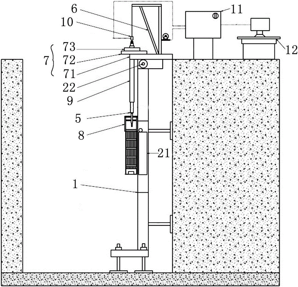
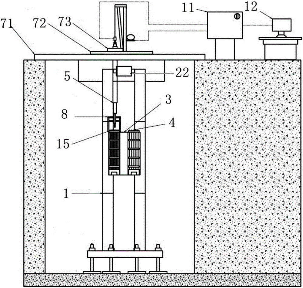
[0058] An underwater dismantling and repairing device for spent fuel assemblies of pressurized water reactors, such as figure 1 , figure 2 and image 3 shown, including:

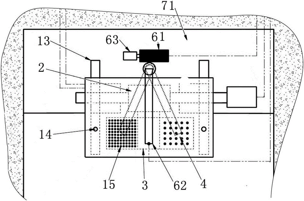
[0059] Column track 1, a mobile trolley arranged on the column track 1, a component temporary storage device 3 and a fuel rod temporary storage device 4 arranged on the mobile trolley, and a rod pulling control platform arranged at the top of the column track 1;

[0060] The rod pulling control platform includes a fuel rod grabbing tool 5 for grabbing fuel rods, a rod pulling lifting platform 6 that controls the lifting of the fuel rod grabbing tool 5, and a rod pulling positioning platform that limits the horizontal position of the fuel rod grabbing tool 5 7.

[0061] The fuel rod grabbing tool 5 includes a cylinder 16, a spring 17, a transmission mechanism 18, an outer tube 19 and a gripping head. During work, when the air cylinder 16 is cut off, the spring 17 impels the transmission mechanism 18 to m...

Embodiment 2

[0078] The difference between this embodiment and Embodiment 1 is that in this embodiment, the structure at the position of the fuel rod grabbing tool 5 is optimized, so that the accuracy and accuracy are higher when grabbing, and the grabbing efficiency is effectively improved. The specific settings are as follows :

[0079] The present invention also includes a double-layer guide plate mechanism 8 arranged on the fuel assembly for precise positioning of the fuel rod grabbing tool 5 . A guide mechanism 9 is also provided on the rod pulling positioning platform 7, and the fuel rod grabbing tool 5 passes through the guide mechanism 9 and extends to a fuel rod grabbing position.

[0080] In the present invention, the double-layer guide plate mechanism 8 includes an E / F guide plate 23 and a clamping mechanism 24; wherein, holes are provided on the E / F guide plate 23, and the diameter of the holes is 1.7 times the distance between the fuel rods, and the holes are arranged diagonal...

Embodiment 3

[0085] The difference between this embodiment and Embodiment 2 is that a pulling force measuring instrument 10 is added in this embodiment to effectively monitor the pulling force of the fuel rod.

[0086] A pulling force measuring instrument 10 is also arranged at the connection between the rod pulling lifting platform 6 and the fuel rod grabbing tool 5, and the pulling force measuring instrument 10 is connected with the control box through a control line.


PUM


Abstract

The invention provides an underwater disassembling repairing process of a spent fuel assembly of a pressurized water reactor, aiming at solving the problems in the prior art that efficiency and safety have deficiency when a fuel rod is replaced at an underwater position with the depth of more than 7m. The underwater disassembling repairing device comprises a stand column rail (1), a movable trolley arranged on the stand column rail (1), an assembly temporary storage device (3) and a fuel rod temporary storage device (4) which are arranged on the movable trolley, and a pulling rod control platform arranged at the top of the stand column rail (1); the pulling rod control platform comprises a fuel rod grasping tool (5) for grasping a fuel rod, a pulling rod hoisting platform (6) for controlling the fuel rod grasping tool (5) to ascend and descend and a pulling rod positioning platform (7) for limiting a horizontal position of the fuel rod grasping tool (5). The underwater disassembling repairing device provided by the invention is suitable for carrying out replacement operation on damaged fuel rods at the underwater position with the depth of more than 7m; the operation is simpler and safer.

Description

technical field [0001] The invention belongs to the technical field of repairing fuel assemblies in the nuclear industry, and relates to an underwater disassembly repairing device for spent fuel assemblies of a pressurized water reactor and a repairing process thereof. Background technique [0002] Fuel assembly is a key core component of a nuclear power plant, and its integrity and damage rate are directly related to the safety and economy of the nuclear power plant. Although the world's nuclear powers have made unremitting efforts to reduce the breakage rate of fuel assemblies, the breakage rate of fuel assemblies is still common. The damage of fuel assemblies not only has a serious impact on the safe operation of the reactor, but also brings significant economic losses to the nuclear power plant, and it is extremely difficult to deal with the damaged fuel. Therefore, the repair of damaged fuel assemblies is the best way to solve this problem. [0003] Due to the strong r...

Claims


Application Information

Patent Timeline
Patent Type & Authority Applications(China)
IPC IPC(8): G21C19/26
CPCG21C19/26Y02E30/30
Inventor 李成业王万金刘晓松陈启兵王立德李文钰李国云江林志李子彦周治江任亮邓鹏宇吴伟吴瑞偶建磊
Owner NUCLEAR POWER INSTITUTE OF CHINA
Why Eureka
Try Eureka