
Planar microstrip patch array antenna

A microstrip patch and array antenna technology, applied in the directions of antennas, electrical components, radiating components, etc., can solve the problem of asymmetrical antenna radiation pattern, differential connection of radio frequency front-end circuits, etc.

Inactive Publication Date: 2017-02-22
HUAYU AUTOMOTIVE SYST +1
View PDF2 Cites 5 Cited by
  • Summary
  • Abstract
  • Description
  • Claims
  • Application Information

AI Technical Summary

Problems solved by technology

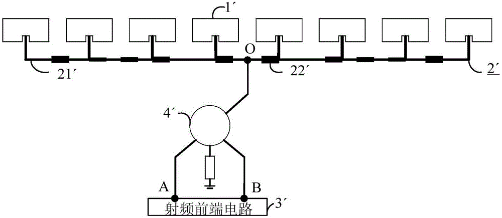
[0007] For above-mentioned deficiencies in the prior art, the purpose of the present invention is to provide a kind of novel planar microstrip patch array antenna, to solve the antenna radiation pattern asymmetry of existing planar microstrip patch array antenna and the differential connection with the radio frequency front-end circuit When you need a dual-port to single-port problem

Method used


Image

  • Planar microstrip patch array antenna
  • Planar microstrip patch array antenna
  • Planar microstrip patch array antenna

Examples


Embodiment Construction

[0026] The specific embodiments of the present invention will be given below in conjunction with the accompanying drawings to elaborate on the functions and features of the present invention.

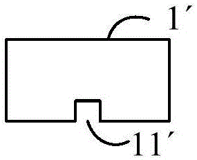
[0027] Planar microstrip patch array antenna of the present invention such as image 3 As shown, it includes a radiation patch array composed of a row (generally an even number) of rectangular radiation patches 1 arranged at equidistant intervals along a straight line. and figure 1 The difference in structure is that mutually symmetrical feeding networks 2 are arranged on both sides of the radiating patch array, and each feeding network 2 is composed of a plurality (generally an even number) of microstrip lines 22 connected by transmission lines 21; in addition, The central positions of the radiating sides on both sides of each radiating patch 1 are provided with mutually symmetrical feeding cutouts 11 (see Figure 4 ), the central feed points of each feed cutout 11 are respectively p...


PUM


Abstract

The invention provides a planar microstrip patch array antenna. The planar microstrip patch array antenna comprises one row of radiation patch array composed of radiation patches which are arrayed along the straight line, wherein feed networks, which are symmetrical mutually, are arranged on two sides of the radiation patch array; feed notches, which are symmetrical mutually, are formed in two central positions of radiation edges on two sides of each radiation patch; and a central feed point of each feed notch is connected with the feed network located on the same side. By adopting the planar microstrip patch array antenna provided by the invention, the problems of an existing planar microstrip patch array antenna that an antenna radiation pattern is asymmetrical and double ports need to be switched to a single port in a differential connection process of a radio frequency front-end circuit can be solved.

Description

technical field [0001] The invention relates to the field of antennas, in particular to a planar microstrip patch array antenna. Background technique [0002] With the rapid development of microwave devices and microwave system technology, short-range radar, as a wireless sensor, has the advantages of being less affected by weather and having a moderate operating distance. Wide range of applications. [0003] Among them, one of the core components of a radar or microwave communication system is an antenna, and there are different types of antennas according to application occasions and system requirements. For example, the horn antenna has the advantages of simple manufacture and high gain, but at the same time has obvious disadvantages such as high cost and large volume, and it is difficult to integrate with the RF front-end circuit. In this regard, the planar microstrip patch array antenna based on the traditional PCB manufacturing process, which can be mass-produced at ...

Claims


Application Information

Patent Timeline
Patent Type & Authority Applications(China)
IPC IPC(8): H01Q1/38H01Q13/08
CPCH01Q1/38H01Q13/08
Inventor 郭剑鹰肖鹏程张枝高石磊房旭龙朱佳南李振华李文宏陆振海韦园园
Owner HUAYU AUTOMOTIVE SYST
Learn More