A general wireless charging system

A wireless charging, general-purpose technology, applied in current collectors, electric vehicles, electrical components, etc., can solve problems such as expensive prices, and achieve the effects of compact shape, lower threshold for use, and strong versatility

Inactive Publication Date: 2019-06-04
SHANGHAI DIANJI UNIV
View PDF4 Cites 0 Cited by
  • Summary
  • Abstract
  • Description
  • Claims
  • Application Information

AI Technical Summary

Problems solved by technology

The current wireless charging devices on the market are all one-to-one wireless charging. To realize one-to-many wireless charging, multiple platforms are required for charging.
Moreover, at this stage, wireless charging technology is still concentrated on high-end devices of a few brand products, and its high price makes this technology not yet fully popularized.

Method used


Image

  • A general wireless charging system
  • A general wireless charging system
  • A general wireless charging system

Examples


specific Embodiment 1

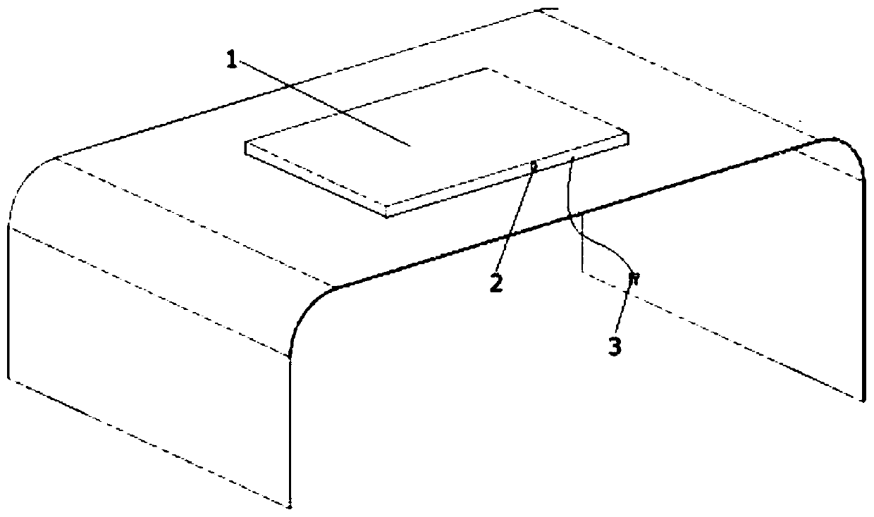
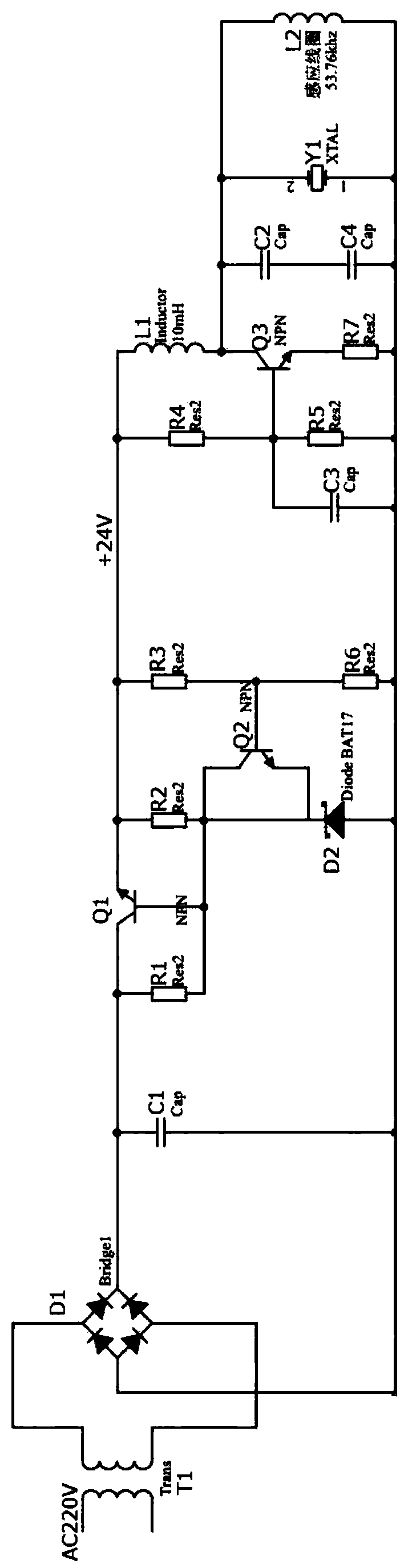
[0017] see figure 1 and Figure 4 , a universal wireless charging system according to the present invention, comprising a housing 1, a wire plug 3 and a control circuit. The control circuit includes a transmitter circuit. The transmitter circuit is arranged on one side of the housing 1. The housing 1 is also provided with a switch 2 for controlling the transmitter circuit. The wire plug 3 is electrically connected to the transmitter circuit. The transmitter circuit includes transformer T1, bridge rectifier circuit D1, filter capacitor C1, capacitor C2, capacitor C3, capacitor C4, transistor Q1, transistor Q2, transistor Q3, Zener diode D2, resistor R1, resistor R2, resistor R3, resistor R4, resistor R5, resistor R6, resistor R7, crystal oscillator Y1, inductor L1 and induction coil L2. The transformer T1 is connected to the bridge rectifier circuit D1, and the filter capacitor C1 is connected in parallel between the bridge rectifier circuits D1. One end of the resistor R1 a...

specific Embodiment 2

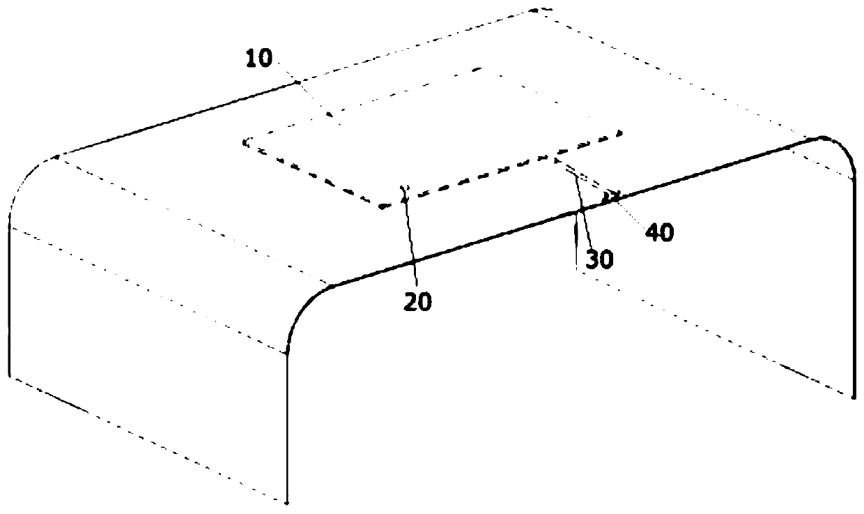
[0021] A universal wireless charging system includes a housing 10, a switch 20, a connecting circuit 30, a charging interface 40 and a control circuit. The components of the control circuit are thin plate structures, and the casing 10 is a plastic film structure. The control circuit is placed on the casing 10 and protected by the plastic casing 10 . 10. The back side of the shell is provided with an adhesive film, and its charging interface 40 uses a USB5V charging interface again, thereby greatly improving the portability of the patent of the present invention. When people use it, they only need to tear off the sticky film, fix it on a certain position such as a table, a coffee table, or directly put it on the table for use. Of course, the present invention can also be directly designed on positions such as coffee table, dining table.

[0022] The patent of the present invention realizes the one-to-many wireless charging function by means of a relatively simple structure and...


PUM


Abstract

The invention discloses a universal wireless charge system which comprises a shell, a wire plug and a control circuit, wherein the control circuit comprises an emitting end circuit and a receiving end circuit; the emitting end circuit is arranged on one side of the shell; a switch for controlling the receiving end circuit is further arranged on the shell; the wire plug is electrically connected with the emitting end circuit; the emitting end circuit comprises a transformer T1, a bridge type rectifier circuit D1, a filter capacitor C1, a capacitor C2, a capacitor C3, a capacitor C4, a triode Q1, a triode Q2, a triode Q3, a voltage stabilizing diode D2, a resistor R1, a resistor R2, a resistor R3, a resistor R4, a resistor R5, a resistor R6, a resistor R7, a crystal oscillator Y1, an inductor L1 and an inductive coil L2. The universal wireless charge system is simple in structure, convenient to carry over, capable of charging power for multiple electrical appliances of different direct-current voltages, and has wide market prospects and relatively high social values.

Description

technical field [0001] The invention relates to the field of wireless charging devices, in particular to a universal wireless charging system. Background technique [0002] Although the charging technologies of wireless charging mobile phones, wireless charging Bluetooth speakers, or wireless charging tablet computers on the market are relatively complete, they are all independent and specific charging systems for specific devices. Moreover, such devices are often high-end flagship products among similar products, and are expensive. However, few companies have set foot in this field in terms of how to make huge ordinary devices also obtain wireless charging functions and further lower the threshold of wireless charging technology. [0003] Wireless charging technology was originally designed to free people from messy charging cables. However, although the current wireless charging technology frees people from the shackles of charging cables, each device is independent of e...

Claims


Application Information

Patent Timeline
Patent Type & Authority Patents(China)
IPC IPC(8): H02J7/02H02J50/10
CPCH02J7/025
Inventor 杜浩明李恩泽王成
Owner SHANGHAI DIANJI UNIV
Why Eureka
Try Eureka