
Magnetic auxiliary power machine

A power machine and power technology, applied in the direction of electromechanical devices, electric components, control mechanical energy, etc., can solve problems such as limitations, and achieve the effects of reduced output power, large power output, and low processing and manufacturing costs

Inactive Publication Date: 2017-02-22
刘长彪
View PDF0 Cites 4 Cited by
  • Summary
  • Abstract
  • Description
  • Claims
  • Application Information

AI Technical Summary

Problems solved by technology

The use of water conservancy, wind power and solar power generation is recognized as clean energy, but due to the bottleneck problem of power transportation and storage, there are many restrictions in application

Method used


Image

  • Magnetic auxiliary power machine
  • Magnetic auxiliary power machine
  • Magnetic auxiliary power machine

Examples


Embodiment Construction

[0027] The technical solution of the present invention will be further explained and illustrated through specific embodiments below in conjunction with the accompanying drawings.

[0028] See attached picture.

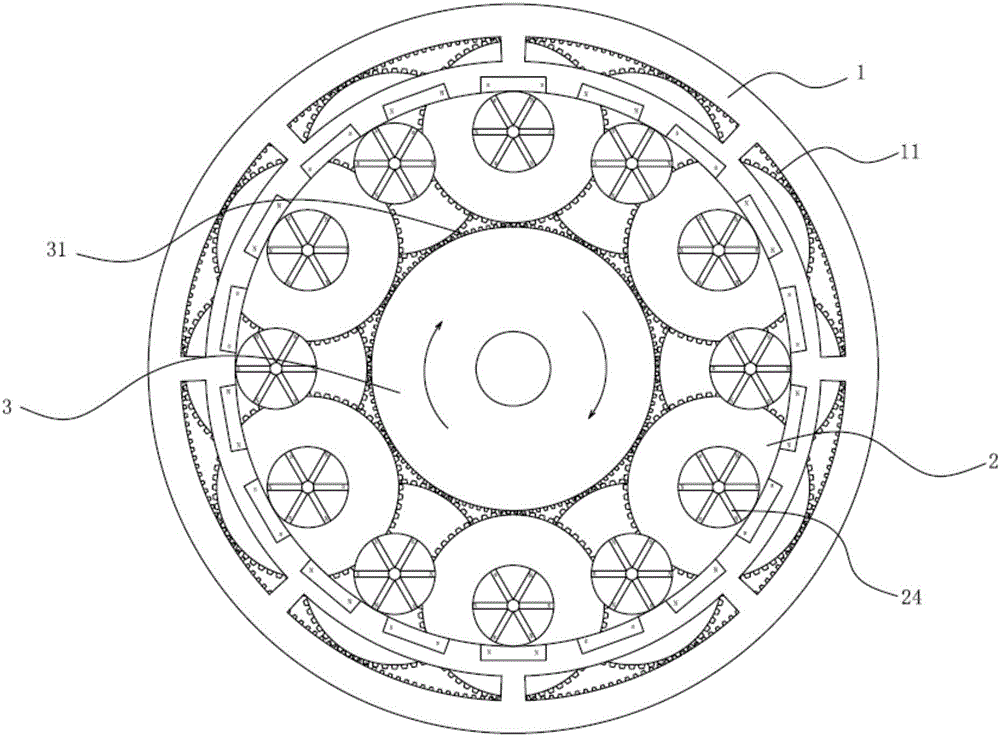
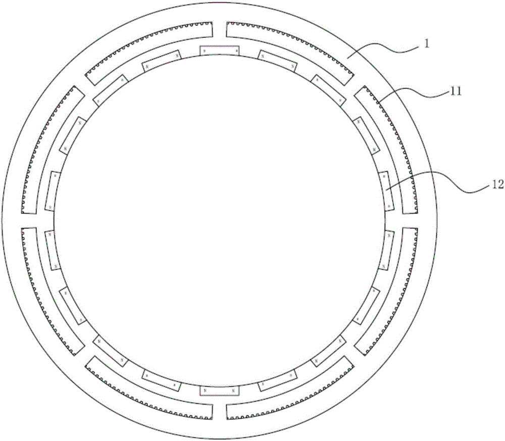
[0029] The magnetic auxiliary power machine of the present invention includes a motor and a magnetic auxiliary device, wherein the magnetic auxiliary device components are composed of three parts: a stator 1, a plurality of rolling magnetic rings 2 and a rotor 3, wherein the stator 1 is provided with an inner ring gear 11 along the circumferential direction , The rotor 3 is composed of an output shaft and an outer ring gear 31 arranged on the output shaft, the rotor 3 is coaxially arranged in the stator 1, and a driving chamber is arranged between them, and the rolling magnetic rings 2 are evenly arranged in the driving chamber along the outer periphery of the rotor.

[0030] The rolling magnetic ring 2 includes a main shaft 21, the main shaft 1 is provided with a gear...


PUM


Abstract

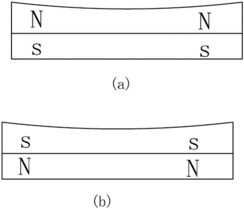
A magnetic auxiliary power machine comprises a motor and a magnetic auxiliary device, wherein the magnetic auxiliary device comprises a stator and a rotor, the rotor is coaxially arranged in the stator, a driving cavity is arranged between the stator and the rotor, the stator is provided with inner ring gears along a circumferential direction, outer ring gears are arranged on an outer surface of the rotor along the circumferential direction, a plurality of rolling magnetic rings are arranged in the driving cavity and are uniformly arranged along the periphery of the rotor, each rolling magnetic ring comprises a main shaft, gears are arranged on the main shaft and are engaged with the inner ring gears and the outer ring gears, a power magnetic disc is also arranged on the main shaft, a plurality of first magnets are arranged on the power magnetic disc and are uniformly and radially arranged, an S pole or an N pole is arranged at an outer end part of each first magnet, the magnetic polarities of outer end parts of two adjacent first magnets are opposite, a magnetic ring is arranged on the stator along the circumferential direction and comprises a plurality of second magnets matched with the first magnets on the magnetic disc, the magnetic polarities of surfaces, corresponding to the rotor, of two adjacent magnets are opposite, one end of the rotation shaft of the rotor (3) is connected with the motor, and the other end of the rotation shaft is a power output.

Description

technical field [0001] The invention relates to the field of power machinery, in particular to a magnetic auxiliary power machine. Background technique [0002] The development and progress of human society cannot be separated from the development and application of energy. For a long time, people's life and production have mainly relied on natural resources such as coal, natural gas, and oil, which have caused great pollution to the environment. The use of water conservancy, wind power and solar power to generate electricity is recognized as clean energy. However, due to the bottleneck problem of power transportation and storage, there are many restrictions in application. At present, permanent magnet is a kind of energy storage body, which has been gradually recognized by people. Magnetic energy can be converted into mechanical energy and electrical energy, and the application of magnetic energy is becoming more and more extensive. Contents of the invention [0003] To...

Claims


Application Information

Patent Timeline
Patent Type & Authority Applications(China)
IPC IPC(8): H02K7/116H02K7/20
CPCH02K7/116H02K7/20
Inventor 刘长彪
Owner 刘长彪
Learn More