High linearity sine wave generator followed by clock multiplier dividing

A sine wave generator, high linearity technology, applied in the direction of electrical components, etc., can solve the problems of inability to achieve frequency stability, linearity cannot be improved, large capacitance value, etc., to achieve simple design and implementation, high linearity, and improved linearity degree of effect

Active Publication Date: 2017-02-22
JIAXING NAJIE MICROELECTRONICS TECH
View PDF8 Cites 0 Cited by
  • Summary
  • Abstract
  • Description
  • Claims
  • Application Information

AI Technical Summary

Problems solved by technology

The current general sine wave generator ( figure 1 As shown), the output frequency has a great influence on the inconsistency of the resistance and capacitance and the temperature change, so the frequency stability cannot be achieved
The linearity is also affected by the operational amplifier and cannot be improved
If low-frequency frequency output is required, the capacitor value needs to be large, resulting in a large area, and the most serious ones cannot be based on the chip but must be connected externally

Method used


Image

  • High linearity sine wave generator followed by clock multiplier dividing
  • High linearity sine wave generator followed by clock multiplier dividing
  • High linearity sine wave generator followed by clock multiplier dividing

Examples


Embodiment 1

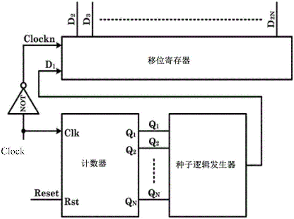
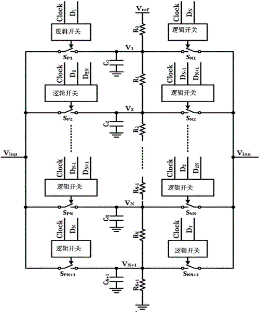
[0024] see figure 1 , figure 2 and image 3 , a high linearity sine wave generator except clock multiple follower, including a reference voltage input terminal Vref, a ground terminal, a fully differential amplifier and a plurality of series voltage dividing resistors, the voltage dividing resistors include the zero resistance R 0 , the first resistor R 1 , the second resistance R 2 ...the N+2th resistor Rn +2 , the zero resistance R 0 One end of is connected to the reference voltage input end, and the N+2th resistor Rn +2 The resistor is connected to the ground terminal, and a first voltage output point V 1 , the second voltage output point V2...the N+1th voltage output point V N+1 . Among them, the first voltage output point is set at the zero resistance R 0 with the first resistor R 1 Between, and so on, the setting position of N+1 voltage output points is between two voltage divider resistors.

[0025] Such as figure 2 , the first voltage output point V 1 To...

Embodiment 2

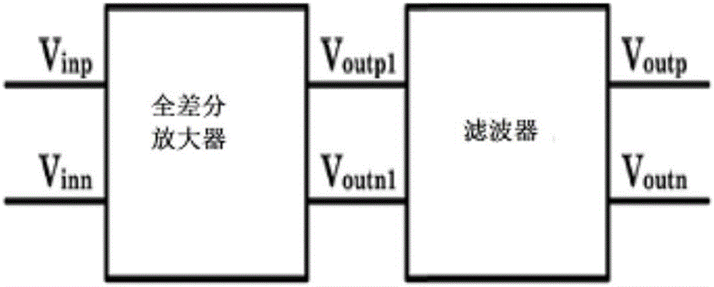
[0043] see Figure 4 , input a stable frequency clock signal from the crystal oscillator to a high linearity sine wave generator followed by clock multiples. In addition to the high linearity sine wave generator followed by the clock multiple, the differential output clock follows the stable frequency sine wave signal to the substrate of the sensor, and the positive terminal outputs V outp Connect the upper substrate V of the sensor st , the negative terminal outputs V outn Connect the lower substrate V of the sensor sb [The connection can also be reversed to output V for the positive terminal. outp Connect the lower substrate V of the sensor sb , the negative terminal outputs V outn Connect the upper substrate V of the sensor st 】. The substrate of the sensor V ctr Connect the negative terminal input of the front-end amplifier, connect the feedback capacitor C f One end, connected to the feedback resistor R f one end. The positive input of the front-end amplifier i...


PUM


Abstract

The invention relates to a high linearity sine wave generator followed by clock multiplier dividing. The high linearity sine wave generator includes a reference voltage input end, a grounding end, a fully differential amplifier and a plurality of serially connected voltage divider resistors, further includes a non-gate and a counter connected to an external clock signal, a seed logic generator connected with a counter, and a shift register connected with the seed logic generator, the clock signal input end of the shift register is connected with the output end of the non-gate, the shift register successively controls a first 1+H positive switch and an N+1-H negative switch to be turned on through a logic switch, H is in an integer being less than and equal to N and is greater than and equal to 0, so that the fully differential amplifier outputs sine waves. According to the invention, the problems of low frequency stability and bad linearity can be solved.

Description

[0001] 【Technical field】 [0002] The present invention relates to electronic circuits, in particular to a high-linearity sine wave generator following clock multiples. [0003] 【Background technique】 [0004] Sine wave generators can be used in many fields, such as sensor carrier demodulation, communication reference oscillators, etc. In these application fields, frequency stability and linearity are the most important parameters of the sine wave generator, which directly determine the performance of the application system. The current general sine wave generator ( figure 1 As shown), the output frequency has a great influence on the inconsistency of the resistance and capacitance and the temperature change, so the state of frequency stability cannot be achieved. This linearity is also affected by the operational amplifier and cannot be improved. If low-frequency frequency output is required, the capacitor value needs to be large, resulting in a large area, and the most ser...

Claims


Application Information

Patent Timeline
Patent Type & Authority Applications(China)
IPC IPC(8): H03B28/00
CPCH03B28/00
Inventor 李荣宽
Owner JIAXING NAJIE MICROELECTRONICS TECH
Why Eureka
Try Eureka