Novel circuit board punching equipment

A technology for punching equipment and circuit boards, which is applied in the direction of printed circuits, printed circuit manufacturing, electrical components, etc., can solve the problems of increasing the production cost of circuit boards, the wear of punch pins, and affecting work, so as to ensure drilling efficiency and drilling efficiency. Hole quality, improved replacement efficiency, and easy operation

Inactive Publication Date: 2017-02-22
南京万云信息技术有限公司
View PDF0 Cites 2 Cited by
  • Summary
  • Abstract
  • Description
  • Claims
  • Application Information

AI Technical Summary

Problems solved by technology

During the production process of the circuit board, it is necessary to drill the circuit board. The function of the drilling is to provide a bridge for the conduction between the subsequent layers, and at the same time drill the alignment holes for the post-process. The current drilling equipment for the circuit board, The drilling efficiency is low, and the quality of the drilling cannot be guaranteed, which leads to a high scrap rate of the circuit board and increases the production cost of the circuit board; at the same time, due to long-term work, the perforating needle is seriously worn, and it takes time and effort to replace it, which affects Work

Method used


Image

  • Novel circuit board punching equipment
  • Novel circuit board punching equipment
  • Novel circuit board punching equipment

Examples


Embodiment Construction

[0017] The present invention will be further explained below in conjunction with the accompanying drawings and specific embodiments. It should be understood that the following specific embodiments are only used to illustrate the present invention and are not intended to limit the scope of the present invention.

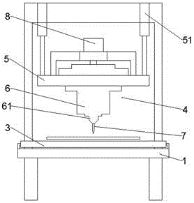
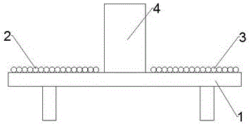
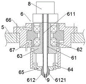
[0018] Such as Figure 1-4 As shown, a new type of circuit board punching equipment includes a workbench 1, a feeder 2, a discharger 3 and a puncher 4 arranged between the feeder 2 and the discharger 3 are arranged on the workbench 1 , the puncher 4 comprises a lifting plate 5, a clamping device 6 arranged on the lifting plate 5 and a perforating needle 7 clamped by the clamping device 6, the first cylinder 51 is provided at both ends of the lifting plate 5, and the clamping device 6 includes a chuck 61, a bearing 62, a push sleeve 63, a guide rod 64, a locking plate 65, a second cylinder 66 and a piston 67 arranged in the second cylinder 66, and the chuck 61 includes...


PUM


Abstract

The invention provides novel circuit board punching equipment. The novel circuit board punching equipment includes a workbench, wherein the workbench is provided with a feeding machine, a discharging machine and a puncher; the puncher includes a lifting plate, a clamping device and a punching needle; two ends of the lifting plate are each provided with a first cylinder; the clamping device includes a clamping head, bearings, a push sleeve, guide bars, a locking plate, a second cylinder and a piston which is arranged in the second cylinder; the clamping head includes a guide pipe and a clamping part; the upper end of the guide pipe is enclosed; the clamping part is formed by at least three clamping lobes; the top end of the clamping head is connected with an electric rotating machine; a through hole being adapted to the guide pipe is formed in the push sleeve; an inner cone hole is formed in the locking plate; the guide pipe of the clamping head penetrates through the through hole of the push sleeve; the clamping part is arranged in the inner cone hole of the locking plate; and one end of the guide bar is connected with the locking plate, and the other end of the guide bar is connected with the push sleeve. The novel circuit board punching equipment has the advantages that the clamping device is simple in structure and can firmly clamp punching needles with different size; and as exchanging of the punching needles is simple and quick, the exchanging efficiency of the punching needles can be improved, and the punching efficiency and the punching quality can be guaranteed.

Description

technical field [0001] The invention relates to the technical field of punching equipment, in particular to a novel circuit board punching equipment. Background technique [0002] The circuit board makes the circuit miniaturized and intuitive, and plays an important role in mass production of fixed circuits and optimizing the layout of electrical appliances. Circuit boards can be called printed circuit boards or printed circuit boards and rigid-flex boards. [0003] At present, the existing circuit board production method is: utilize a circuit board punching machine to punch mounting holes on a large circuit board, and then cut the large circuit board into small circuit boards one by one. During the production process of the circuit board, it is necessary to drill the circuit board. The function of the drilling is to provide a bridge for the conduction between the subsequent layers, and at the same time drill the alignment holes for the post-process. The current drilling eq...

Claims


Application Information

Patent Timeline
Patent Type & Authority Applications(China)
IPC IPC(8): H05K3/00
CPCH05K3/0047H05K2203/0214
Inventor 王庆文
Owner 南京万云信息技术有限公司
Why Eureka
Try Eureka