

Electric vehicle controller
An electric vehicle controller and controller technology, applied in the direction of circuits, electrical components, and circuit layout on support structures, can solve problems such as labor-intensive, easy-to-short circuit, messy, etc., to achieve reasonable design of the lead-out structure, ensure heat dissipation effect, The effect of reducing manufacturing costs
- Summary
- Abstract
- Description
- Claims
- Application Information
AI Technical Summary
Problems solved by technology
Method used
Image

Examples
Embodiment 1
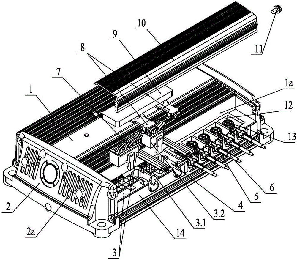
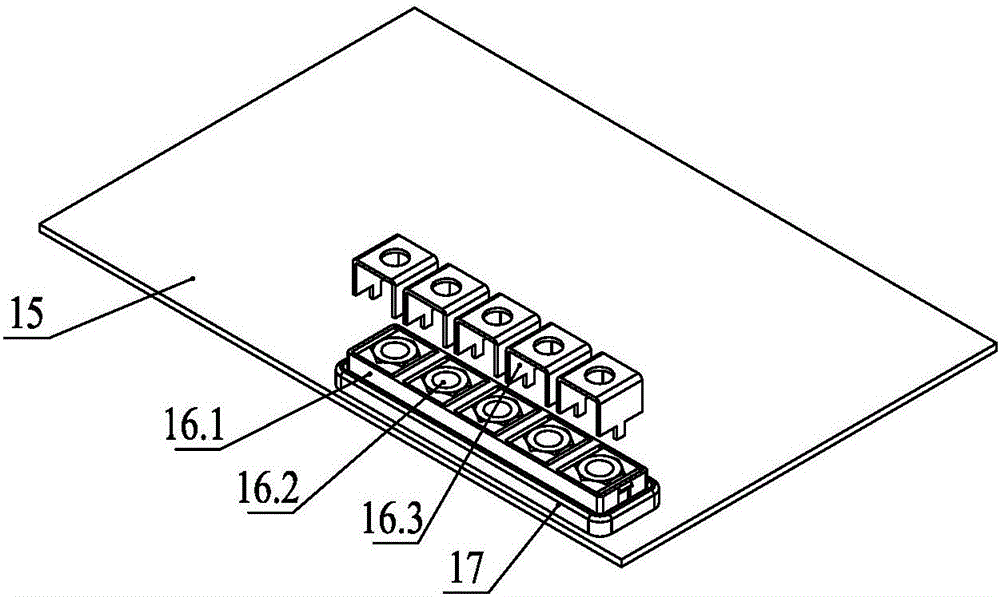
[0041] Such as figure 1 , Figure 5 As shown: the electric vehicle controller in the embodiment is mainly composed of a controller casing and a circuit board 15, the circuit board 15 is installed in the controller casing, and the circuit board 15 is provided with a signal line wiring connector 3, a high-current wiring The terminal 16 and the power semiconductor device 20, the signal line connector 3 is used to connect the control signal line 7, the high current terminal 16 is used to connect the power line or the motor phase line 6; the signal line connector 3 It includes a wiring connector socket 3.1 and a pluggable wiring connector plug 3.2, the wiring connector socket 3.1 and the high-current wiring terminal 16 are arranged on the front side of the circuit board 15, and the front of the controller shell There is a downwardly recessed junction box 1a on the side, and the bottom of the junction box 1a is provided with a through hole corresponding to the shape and size of the w...
Embodiment 2
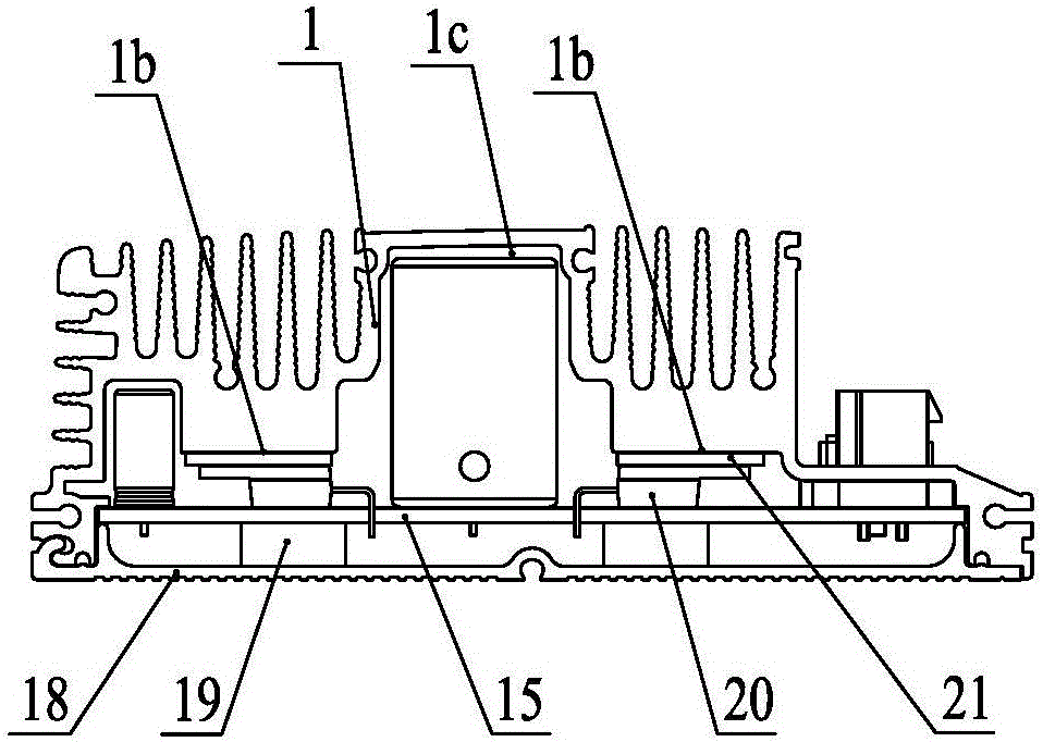
[0063] The difference between this embodiment 2 and embodiment 1 is that the power semiconductor device 20 is pressed differently. 24 combinations implement compression, no support soft rubber pad 19 is provided.
[0064] Such as Figure 13As shown, in Embodiment 2, several large installation through holes 15a are provided on the circuit board 15 outside the power semiconductor device 20, and several large installation through holes 15a are provided on the pressure plate 21 and the housing main body 1 respectively. The small installation through holes 21a and the screw holes corresponding to the installation through holes 15a one by one are installed with a hollow T-shaped head compression post 22 in the large installation through hole 15a, and the central hole of the T-shaped head compression post 22 A compression screw 23 is installed inside, and the compression screw 23 is threadedly connected in the screw hole on the shell main body 1. The inner surface of the head of the...
PUM
 Abstract
Description
Claims
Application Information