

Apparatus to move and preheat metal material
A material and metal technology, applied in the direction of preheating costs, lighting and heating equipment, waste heat treatment, etc., can solve the problems of cooling tunnel walls that require a large amount of coolant, high total weight, and large quantity, so as to optimize heat exchange conditions and prevent Thermal layering, volume reduction effect
- Summary
- Abstract
- Description
- Claims
- Application Information
AI Technical Summary
Problems solved by technology
Method used
Image

Examples
Embodiment Construction
[0047] Reference is made in detail below to the various forms of embodiments of the invention, one or more examples of which are illustrated in the accompanying drawings. Each example is given by way of illustration of the invention and none should be construed as limitation of the invention. For example, features shown and described may be used as part of one embodiment form or in connection with other forms of embodiment to form another embodiment form. It should be understood that the present invention includes all such modifications and variations.
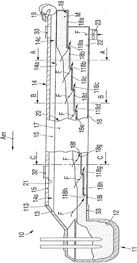
[0048] figure 1 It is used to describe an embodiment form of a device 10 for moving and preheating a metal material M, in particular for a metallurgical smelting process.
[0049] The metal mass M can be melted by a smelting process in a smelting furnace 11 of known type, so it will not be described in detail in this description, but only its parts that have an effect on the device 10 .
[0050] Melting furnace 11, such as ...
PUM
 Abstract
Description
Claims
Application Information