Multi-shaft combined cycle plant, and control device and operation method thereof
A technology of combined cycle and operation method, which is applied in the direction of mechanical equipment, steam engine device, engine control, etc., and can solve the problems of start-up time consumption, start-up time consumption of 35-70 minutes, and consumption
- Summary
- Abstract
- Description
- Claims
- Application Information
AI Technical Summary
Problems solved by technology
Method used
Image
Examples
no. 1 approach ”
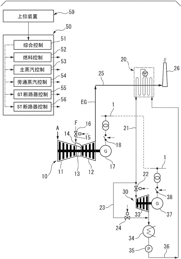
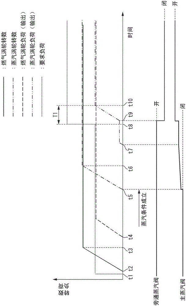
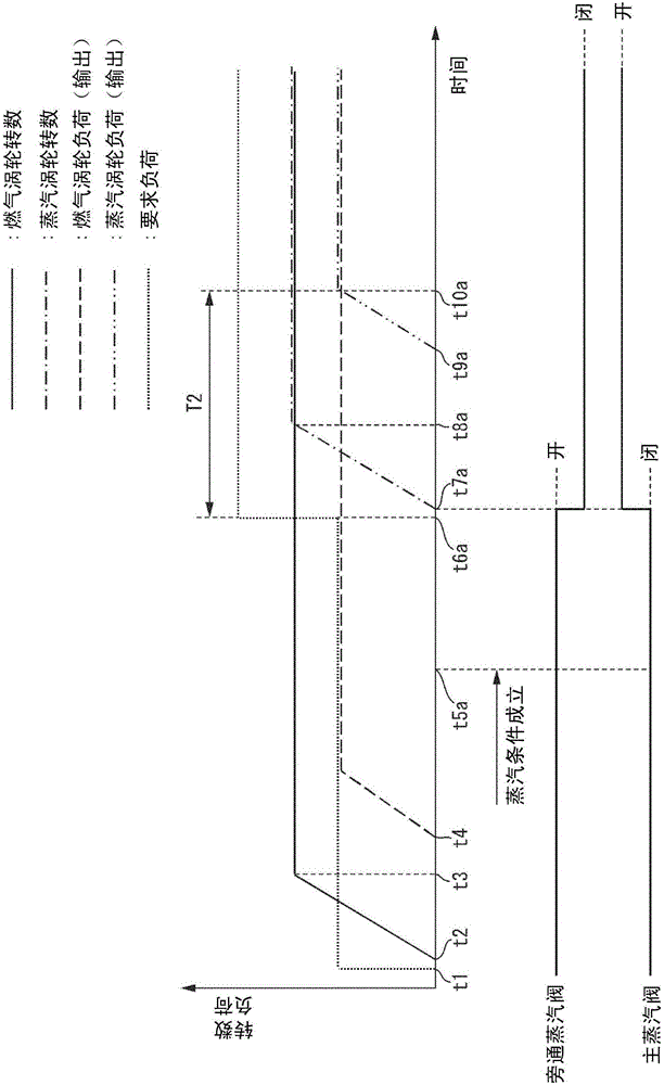
[0046] First, refer to Figure 1 to Figure 6 The first embodiment of the multi-shaft combined cycle plant according to the present invention will be described.
[0047] Such as figure 1 As shown, the multi-shaft combined cycle facility of this embodiment includes a gas turbine 10, a gas turbine generator 17 that generates electricity by driving the gas turbine 10, and a gas turbine generator 17 that electrically connects and disconnects the gas turbine generator 17 and the power system 1. Turbine breaker 18, waste heat recovery boiler 20 that generates steam by using the heat of exhaust gas EG discharged from gas turbine 10, steam turbine 30 driven by steam generated in waste heat recovery boiler 20, steam generated by driving steam turbine 30 The turbine generator 37, the steam turbine breaker 38 for electrically connecting the steam turbine generator 37 with the power system 1 and cutting off, the condenser 34 for turning the steam after driving the steam turbine 30 back in...
no. 2 approach ”
[0099] Next, refer to Figure 9 A second embodiment of the multi-shaft combined cycle plant according to the present invention will be described.
[0100] The multi-shaft combined cycle plant of the present embodiment is a 2on1 type multi-shaft combined cycle plant including two gas turbines 10 , 10 and one steam turbine 30 .
[0101] In this embodiment, a gas turbine generator 17 , a gas turbine circuit breaker 18 , a waste heat recovery boiler 20 , and a chimney 26 are provided for every two gas turbines 10 , 10 .
[0102] The steam outlets of the two waste heat recovery boilers 20 and 20 are both connected to the steam inlet of a steam turbine 30 through the main steam path 21 . A main steam valve 22 is provided in each main steam path 21 . The steam outlet of this steam turbine 30 is connected to the steam inlet of the condenser 34 similarly to the first embodiment. A bypass path 23 branches off from a position upstream of the main steam valve 22 in each of the main ste...
no. 3 approach ”
[0109] Next, refer to Figure 10 A third embodiment of the multi-shaft combined cycle plant according to the present invention will be described.
[0110] The multi-shaft combined cycle plant of this embodiment also includes a gas turbine 10 , a waste heat recovery boiler 20 , and a steam turbine 30 as in the first embodiment. In this embodiment, the gas turbine 10 and the gas turbine generator 17, the steam turbine 30 and the steam turbine generator 37, and the condenser 34 are also the same as those in the first embodiment. In addition, in the present embodiment, the exhaust port of the turbine 12 in the gas turbine 10 is also connected to the chimney 26 through the flue 25 , and the waste heat recovery boiler 20 is installed in the flue 25 . However, in the present embodiment, in the flue 25 , a sub-flue 28 is branched from a position upstream of the waste heat recovery boiler 20 . A sub chimney 29 is connected to this sub flue 28 . The branch part of the secondary flue ...
PUM
 Abstract
Description
Claims
Application Information
 - R&D Engineer
- R&D Manager
- IP Professional
- Industry Leading Data Capabilities
- Powerful AI technology
- Patent DNA Extraction
Browse by: Latest US Patents, China's latest patents, Technical Efficacy Thesaurus, Application Domain, Technology Topic, Popular Technical Reports.
© 2024 PatSnap. All rights reserved.Legal|Privacy policy|Modern Slavery Act Transparency Statement|Sitemap|About US| Contact US: help@patsnap.com


