Rail vehicle brake disk

A technology for rail vehicles and brake discs, applied in the direction of brake discs, brake types, brake components, etc., can solve problems such as the inability to use rail vehicles, and achieve the effects of improved operational reliability, cost advantages, and cost savings

Inactive Publication Date: 2017-02-22
KNORR BREMSE SYST FUR SCHIENENFAHRZEUGE GMBH
View PDF7 Cites 2 Cited by
  • Summary
  • Abstract
  • Description
  • Claims
  • Application Information

AI Technical Summary

Problems solved by technology

Of course, this is only possible with a considerable amount of work and thus costs, including not only actual repair work but also, to a certain extent, unavoidable downtime during which the rail vehicle cannot be used

Method used


Image

  • Rail vehicle brake disk
  • Rail vehicle brake disk
  • Rail vehicle brake disk

Examples


Embodiment Construction

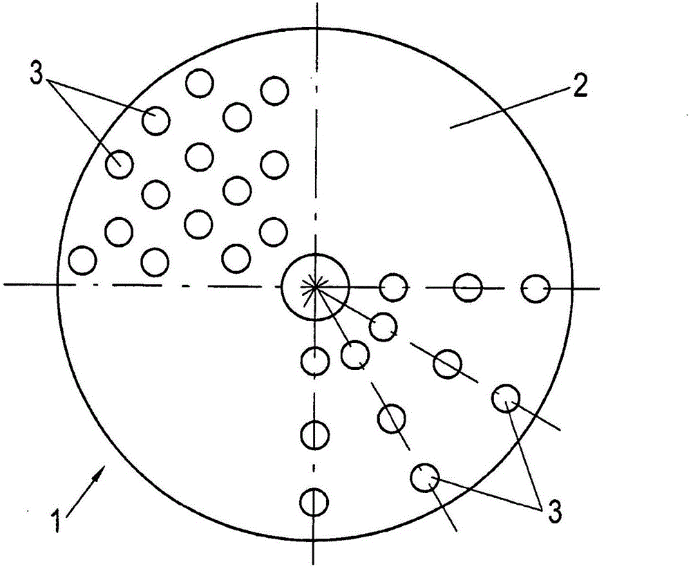
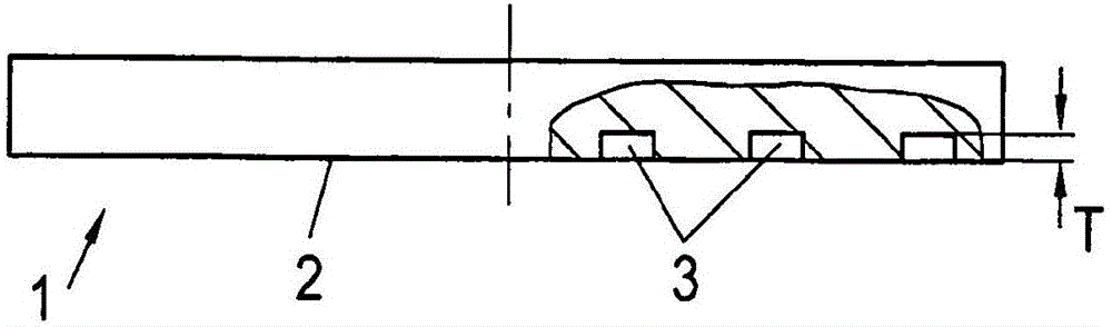
[0027] The drawing shows a one-piece brake disk 1 of steel or cast iron for a rail vehicle, which has an active surface 2 against which a friction body rests during braking.

[0028] According to the invention, the effective face 2 is provided with a plurality of blind openings, which are figure 1 and 2 In the exemplary embodiment shown, this is formed by a blind hole 3 .

[0029] exist figure 1 A substantially haphazard arrangement of blind holes 3 is shown in , as an arrangement possibility, to be precise in the upper left quarter of a circle.

[0030] An ordered positioning of the blind holes 3 can be seen in the lower right quarter of the circle, in which they are oriented not only radially but also multiple concentrically.

[0031] The depth T of the blind hole 3 corresponds here to the maximum permissible amount of wear of the active face 2 .

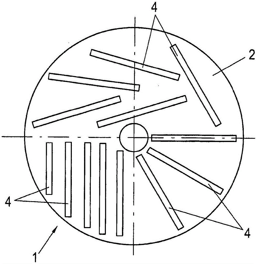
[0032] this is also image 3 and 4 Shown in the example of the invention shown, wherein, blind opening is configured as gr...


PUM


Abstract

The invention relates to rail vehicle brake disk. According to the invention, a one-piece rail vehicle brake disk is made of steel or cast iron, comprises at least one effective surface (2) with which a friction element comes in contact during a braking maneuver, and is designed in such a way that the effective surface (2) has a plurality of blind holes.

Description

technical field [0001] The invention relates to a brake disc for a rail vehicle according to the preamble of claim 1 . Background technique [0002] Primarily for functional reasons, but also for cost reasons, such brake discs are constructed in one piece and have a continuous planar active surface, against which the friction bodies are pressed during braking. [0003] Especially in rail vehicles used in high-speed traffic, many problems arise due to the wear debris generated during braking, which forms accumulations, so-called "Metal-Pickups", which are related to the The brake disc material is welded on the active side. [0004] The direct consequence is that these welded accumulations tear off, resulting in damage or even destruction of the effective surface. [0005] The main influencing parameters for the formation of deposits are the speed of the rail vehicle, i.e. the rotational speed of the wheels, ambient conditions such as moisture, etc., the pressing force of th...

Claims


Application Information

Patent Timeline
Patent Type & Authority Applications(China)
IPC IPC(8): F16D65/00F16D65/12
CPCF16D65/0031F16D65/12F16D2069/004F16D65/0037F16D65/125F16D65/127F16D2200/0013F16D2200/0021F16D2250/0007
Inventor T·格伦瓦尔德N·朗格
Owner KNORR BREMSE SYST FUR SCHIENENFAHRZEUGE GMBH
Why Eureka
Try Eureka