Gate driver controlling a collector to emitter voltage variation of an electronic switch and circuits including the gate driver

A gate driver, power electronic switch technology, applied in electronic switches, circuits, regulating electrical variables, etc., can solve the problems of reducing the performance of the commutation unit, long current switching time, etc.

Inactive Publication Date: 2017-02-22
TM4 INC
View PDF7 Cites 10 Cited by
  • Summary
  • Abstract
  • Description
  • Claims
  • Application Information

AI Technical Summary

Problems solved by technology

However, over-limiting overvoltage may imply longer current switching times, reducing commutation unit performance

Method used


Image

  • Gate driver controlling a collector to emitter voltage variation of an electronic switch and circuits including the gate driver
  • Gate driver controlling a collector to emitter voltage variation of an electronic switch and circuits including the gate driver
  • Gate driver controlling a collector to emitter voltage variation of an electronic switch and circuits including the gate driver

Examples


Embodiment Construction

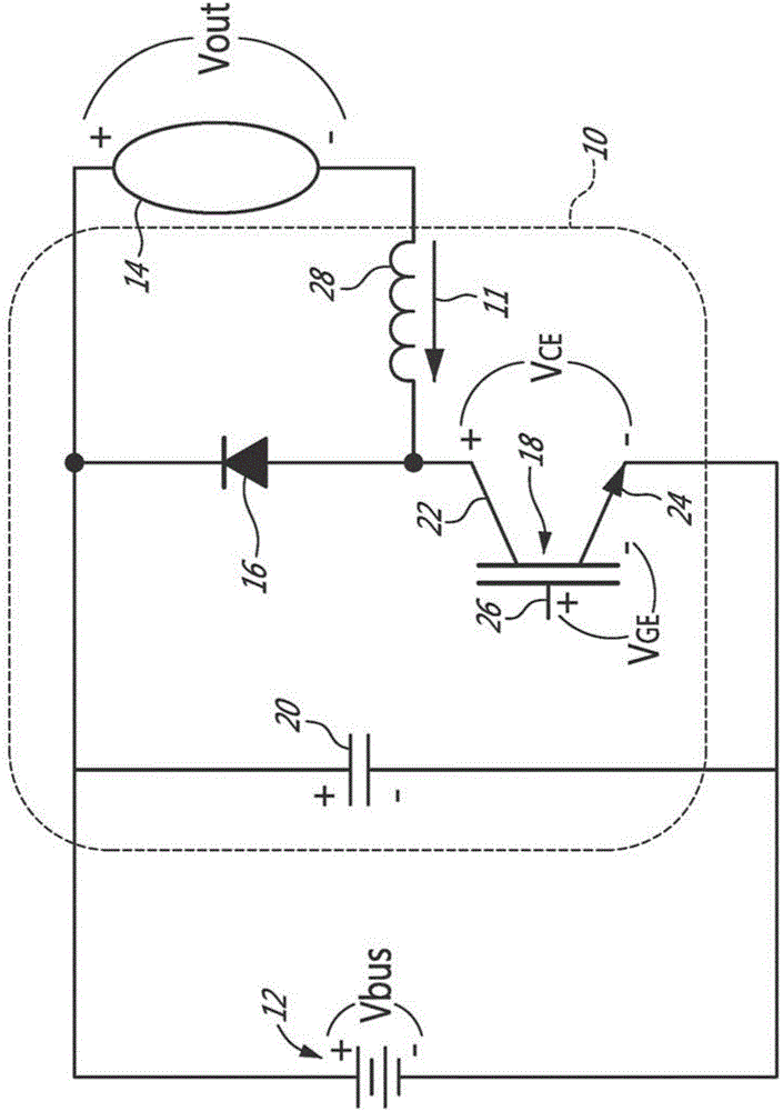
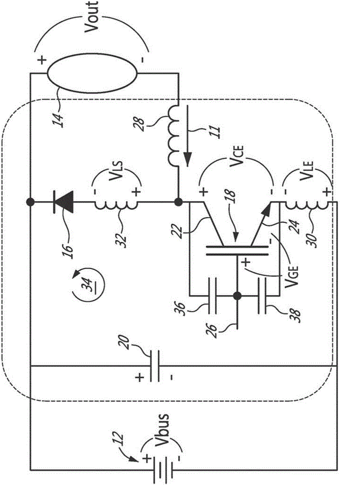
[0044] Aspects of the present disclosure generally address one or more of the problem of overvoltage in the commutation unit when turned off and the problem of excessive recovery current in the commutation unit when it is turned on. In general, it is desirable to reduce the risk of failure of power electronic switches when overvoltage and excessive recovery current are under control. This can be achieved at least in part by keeping the power electronic switches close to their linear region during the commutation process.

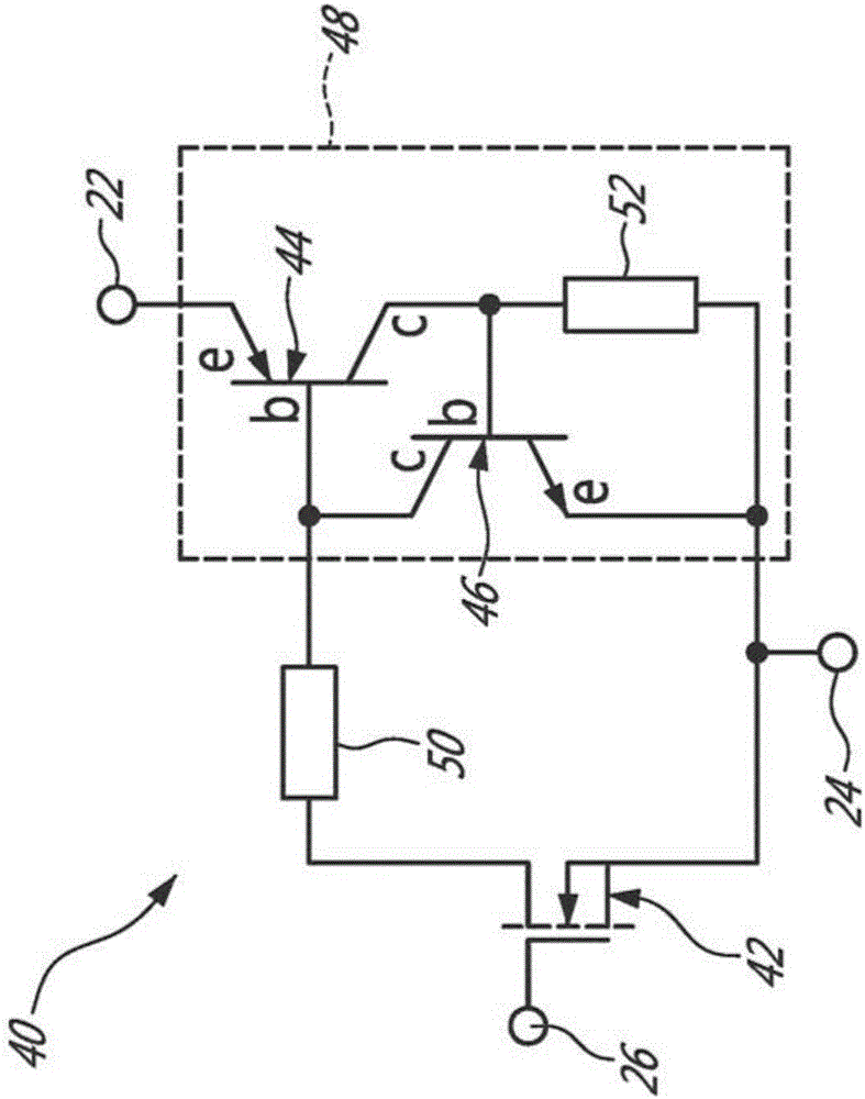
[0045] In one aspect, the present disclosure introduces a gate driver for driving a commutation unit including power electronic switches. A power electronic switch has a collector, a gate and an emitter. The insulation between the collector and the gate forms a parasitic capacitance. The gate driver is configured as a pair of current sources connected to the gate of the power electronic switch, the current sources respectively providing a turn-on current a...


PUM


Abstract

The present disclosure introduces a gate driver used to drive a power electronic switch of a commutation cell. The gate driver comprises a turn-off current source connected to a gate of the power electronic switch and an additional current source. The additional current source is in parallel to the turn-off current source of the gate driver and is configured to control a collector to emitter voltage variation at turn off of the power electronic switch. A circuit combining the gate driver with a commutation cell having a power electronic switch, a circuit combining a pair of gate drivers with a leg having two commutation cells including two power electronic switches and a converter including such circuits are also disclosed.

Description

technical field [0001] This disclosure relates to the field of power electronics. More specifically, the present disclosure relates to gate drivers for controlling collector-to-emitter voltage variations of electronic switches and circuits including the gate drivers. Background technique [0002] Commutation units are commonly used in electronic systems that require switching voltage sources, including DC-DC converters and DC-AC converters. figure 1 is the ideal circuit diagram of a conventional commutation unit with a single power electronic switch and a single freewheeling diode with a voltage source and a current load. The commutation unit 10 converts the DC voltage V from the voltage source 12 (or from the capacitor 20) bus converted to a current source I out 11 (or inductance), which typically generates an appropriate voltage V for the load 14 out , the load 14 can be a resistive load or a motor, etc. A commutation unit 10 includes a freewheeling diode 16 and a co...

Claims


Application Information

Patent Timeline
IPC IPC(8): H02M1/08H02M3/155H02M7/537
CPCH02M1/34H03K17/163H03K17/168Y02B70/10H02M1/346H02M1/0058H02M1/08H03K17/08104H03K17/08116
Inventor J-M.西尔
Owner TM4 INC
Why Eureka
Try Eureka