Linear magnetic resistance catapult

A catapult and reluctance technology, applied in the direction of launch/drag transmission, etc., can solve the problems of pressure drop, complex structure, high manufacturing cost, etc.

Inactive Publication Date: 2017-03-08
柳峰
View PDF0 Cites 0 Cited by
  • Summary
  • Abstract
  • Description
  • Claims
  • Application Information

AI Technical Summary

Problems solved by technology

The biggest technical problem is how to prevent leaks from causing pressure drops
Although the existing electromagnetic catapult technology is superior to the steam catapult, the manufacturing cost is high, the structure is complicated, and the control is difficult. In particular, the cooperation of high-current power storage equipment and permanent magnet materials is required to achieve the ejection effect.

Method used


Image

  • Linear magnetic resistance catapult
  • Linear magnetic resistance catapult
  • Linear magnetic resistance catapult

Examples


Embodiment Construction

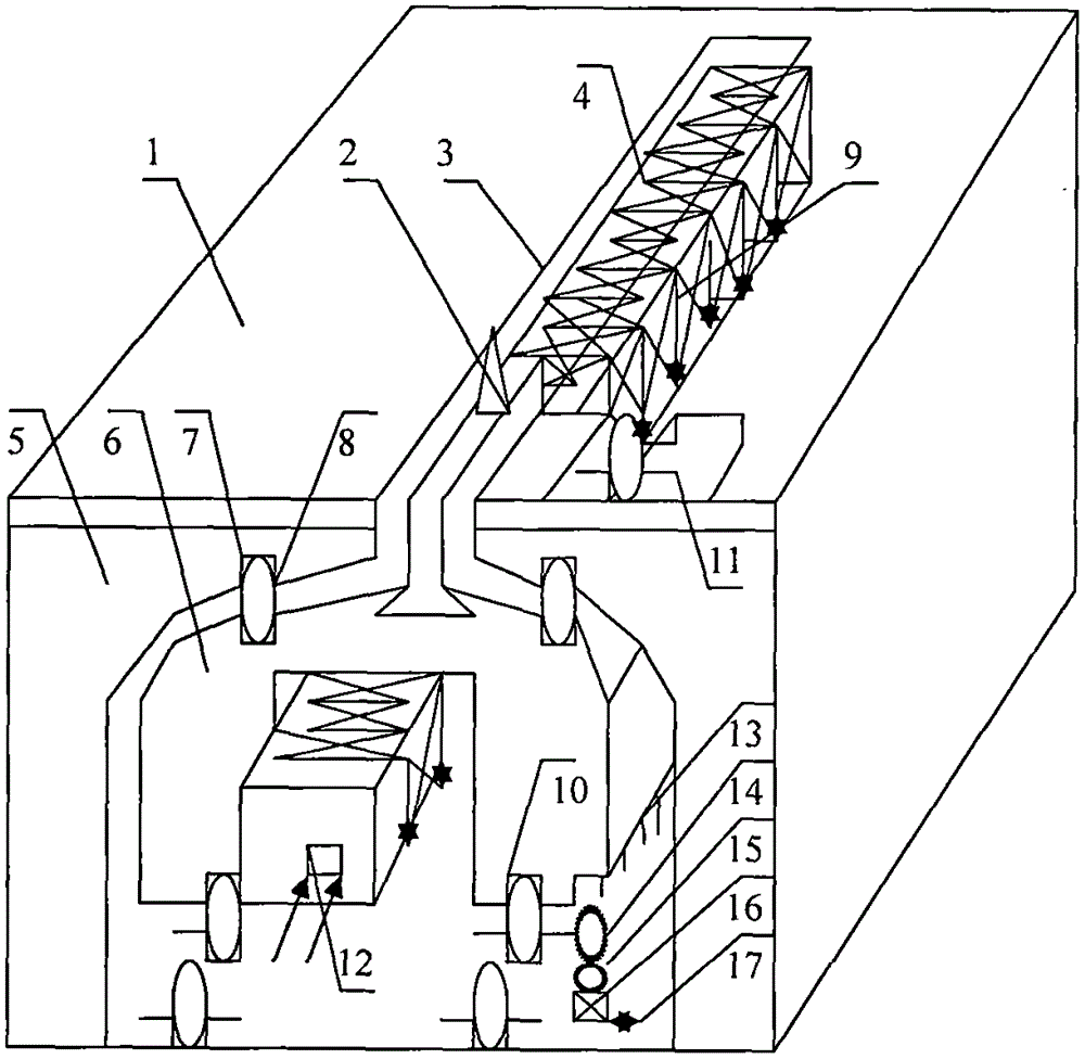
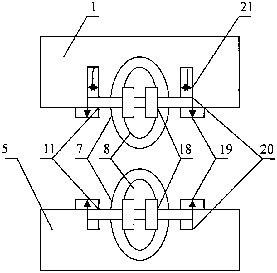
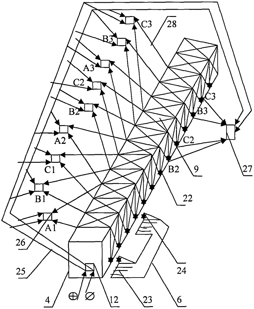
[0027] figure 1 The linear reluctance catapult shown is that a catapult cabin 5 is set in the hull, and a stator 4 is arranged in the middle of the bottom plate of the catapult cabin 5; the pulley holes 7 on both sides of the stator 4 will be equipped with bearings and shafts. The sliding wheel 8 of 11 is installed in the pulley hole 7 and the grid shaft hole; the stator core and the three-phase coil winding 9 are wound in three walls in each grid of the stator 4. The phase coil windings 9 are provided with A, B, C armature joints, Hall position receivers and armature threads; the mover 6 is arranged outside the stator 4 and the slot provided with the sliding groove 10 is arranged on the sliding wheel 8. In the inner wall of the mover 6, the reluctance of the core slot teeth is set, and the reverse wheel teeth 13 are arranged at the left bottom end of the mover 6; the reverse gear 14 and the transmission gear 15 and the motor 16 are arranged on the bottom plate of the ejection b...


PUM


Abstract

The invention provides a linear magnetic resistance catapult. A catapulting bin 5 is arranged in a hull, a deck 1 and a linear groove 3 are arranged at the upper end of the catapulting bin 5, sliding wheel holes 7 and shaft holes are formed in base plates on two sides of the catapulting bin 5 and the deck 1, sliding wheels 8 are arranged in the sliding wheel holes 7, and shafts 11 are arranged at the centers of the sliding wheels 8. A stator 4 is arranged in the middle of a base plate of the catapulting bin 5, 12-120 groups of iron cores are arranged on three wall faces of the stator 4 and are wound with three-phase coil windings 9, and Hall position receivers are arranged in the three-phase coil windings 9. An armature controller connected with the three-phase coil windings 9 and a power transmission grid arrangement room 12 are arranged in the stator 4. An active cell 6 is arranged on the periphery of the stator 4, sliding grooves 10 are formed in the upper ends of two sides and the bottom end of the active cell 6, reversing gear teeth 13 are arranged at the bottom end of the left side of the active cell 6, a reversing gear 14, a transmission gear 15 and an electric motor 16 are arranged on the base plate of the catapulting bin 5 at the lower end of the reversing gear teeth 13, a tackle 17 is arranged on the electric motor 16, and a tractor 2 is arranged on a pushing plate of the active cell 6.

Description

Technical field [0001] The linear magnetoresistive catapult of the present invention relates to a catapult used to accelerate the take-off of a carrier-based aircraft on a national defense aircraft carrier when it takes off. [0002] Background technique: [0003] The linear magnetoresistive catapult of the present invention is inspired by the graphic patterns in the materials of the steam catapult, hydraulic catapult and electromagnetic catapult invented by the predecessors. [0004] Although the steam catapult and electromagnetic catapult invented by the predecessors can make the carrier aircraft take off quickly, the difficulty of the structure of the steam catapult is not only to allow the structure of the driving piston to move freely in the cylinder gap, but also to maintain the necessary Work pressure. The biggest technical problem is how to prevent leaks from causing pressure drops. Although the existing electromagnetic catapult technology is superior to the steam catapult,...

Claims


Application Information

Patent Timeline
Patent Type & Authority Applications(China)
IPC IPC(8): B64F1/06
Inventor 柳峰
Owner 柳峰
Why Eureka
Try Eureka