Three-stage high-vacuum oil filter system

A high-vacuum, oil-filtering technology, which is applied in the direction of lubricating compositions, etc., can solve problems such as difficult cleaning, cracked and damaged heat exchange tubes, and secondary pollution of oil bodies, so as to disturb the direction of air flow, strengthen the separation effect, and ensure the heat exchange effect Effect

Active Publication Date: 2017-03-08
山东沃特润滑科技有限公司
View PDF16 Cites 4 Cited by
  • Summary
  • Abstract
  • Description
  • Claims
  • Application Information

AI Technical Summary

Problems solved by technology

[0003] Therefore, the present invention proposes a three-stage high-vacuum oil filter system, which solves the problem of easy clogging of the spray wings or nozzles of the traditional vacuum oil filter system, difficulty in cleaning, poor oi

Method used


Image

  • Three-stage high-vacuum oil filter system
  • Three-stage high-vacuum oil filter system
  • Three-stage high-vacuum oil filter system

Examples


Embodiment Construction

[0033] The following will clearly and completely describe the technical solutions in the embodiments of the present invention with reference to the accompanying drawings in the embodiments of the present invention. Obviously, the described embodiments are only some, not all, embodiments of the present invention. Based on the embodiments of the present invention, all other embodiments obtained by persons of ordinary skill in the art without creative efforts fall within the protection scope of the present invention.

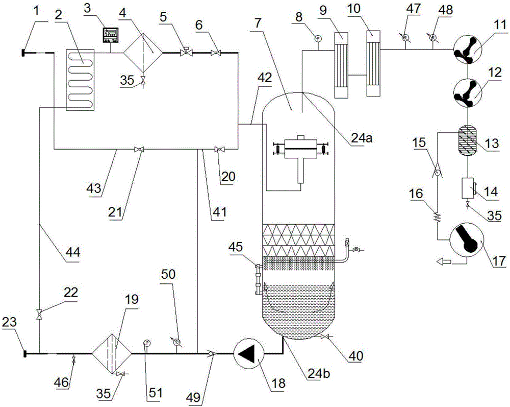
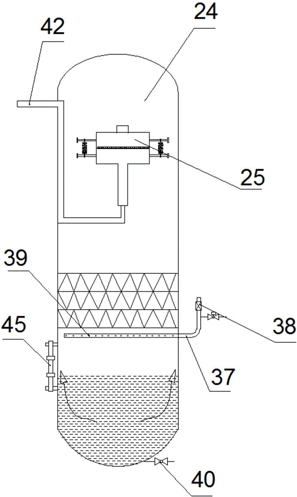
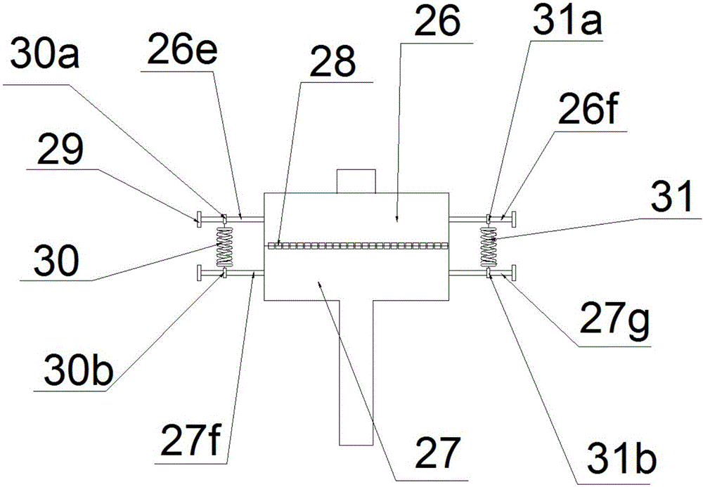
[0034] Such as Figures 1 to 12 As shown, the three-stage high vacuum oil filter system includes oil inlet 1, pipeline turbulence heater 2, constant temperature controller 3, primary filter 4, oil supply solenoid valve 5, oil inlet valve 6, vacuum separation device 7, vacuum Table 8. The first tube heat exchanger 9, the second tube heat exchanger 10, the three-stage Roots pump 11, the two-stage Roots pump 12, the gas-liquid separation tank 13, the water storage dev...


PUM


Abstract

The invention provides a three-stage high-vacuum oil filter system, comprising a vacuum separation system, comprising a vacuum tank and an atomizer arranged in the upper space in the vacuum tank. The three-stage high-vacuum oil filter system has the advantages that as an oil circuit outlet is added, oil can be turned into oil droplets more thoroughly and can be atomized better; as an oil circuit is divided into two paths by a Y-shaped oil spout, which is equivalent to a sudden pressure reduction, oil and water gain a wider diffusion range at the oil circuit outlet, atomizing is more thorough, and it is easier to make separation.

Description

technical field [0001] The invention relates to the field of lubricating oil production and processing, in particular to a three-stage high vacuum oil filtering system. Background technique [0002] Vacuum oil filter is designed according to the principle of different boiling points of water and oil. Vacuum oil filter includes primary filter, vacuum heating tank, oil pump, filter device, condenser (condenser) and vacuum pump. The vacuum pump draws the air in the vacuum heating tank from the gas phase outlet of the vacuum heating tank to form a vacuum. Under the action of atmospheric pressure, the external oil passes through the primary filter to remove larger particles, and then enters the heating zone in the vacuum heating tank. The heated oil is separated into a semi-mist by the rapid rotation of the spray wings, and the water in the oil evaporates rapidly into water vapor, and the mixed air is continuously sucked into the condenser by the vacuum pump, and the water vapor ...

Claims


Application Information

Patent Timeline
IPC IPC(8): C10M177/00
CPCC10M177/00
Inventor 赵奇
Owner 山东沃特润滑科技有限公司
Why Eureka
Try Eureka