Mooring rope protector for building
A protector and construction technology, applied in the direction of textile cables, textiles and papermaking, etc., can solve the problems of reducing the safety of steel ropes and breaking them, so as to improve the service life and safety of use, ensure safety, and improve protection The effect of the characteristic
- Summary
- Abstract
- Description
- Claims
- Application Information
AI Technical Summary
Problems solved by technology
Method used
Image

Examples
Embodiment 1
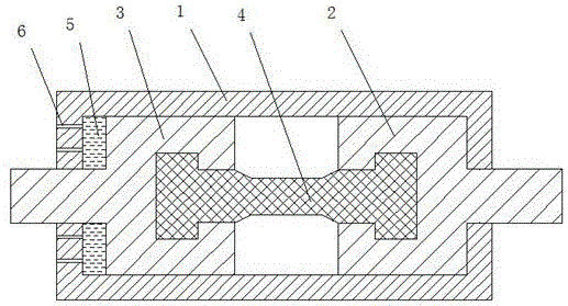
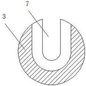
[0028] Such as figure 1 , 2 As shown, a construction cable protector of the present invention includes a housing 1, a first connecting piece 3, a second connecting piece 2, and a breaking piece 4, and the first connecting piece 3 and the second connecting piece 2 are pulled The breaking piece 4 is connected, and the housing 1 is sleeved outside the breaking piece 4, the first connecting piece 3, the second connecting piece 2, and the breaking piece 4. When the breaking piece 4 is broken, the casing 1 bears the first The tension between the connecting piece 3 and the second connecting piece 2.
[0029] A buffer chamber 5 is provided between the first connecting piece 3 or the second connecting piece 2 and the housing 1, and a small hole 6 communicating with the outside of the housing 1 is provided on the side wall of the buffer chamber 5; After being pulled off, the first connecting piece 3 or the second connecting piece 2 squeezes the buffer chamber 5 to drain or exhaust the...
Embodiment 2
[0035] In the structure of embodiment 1, a paint bag and a solvent bag are respectively housed in the buffer cavity 5, the paint bag and the solvent bag are all made of elastic capsules as containers, air and pigment are housed in the paint bag, gasoline, paint, etc. are housed in the solvent bag. The pigment in the bag is composed of the following powders by weight: 30-50 parts of cinnabar, 40-50 parts of 300 mesh ground calcium carbonate, 20-30 parts of red coral, 15-22 parts of polyoxyethylene oleate, 16-33 Parts of polyethylene wax, 40-50 parts of luminous powder, 33-45 parts of garnet, 10-30 parts of hematite, 3-9 parts of nano-silver powder, 1-9 parts of zoisite, 11-16 parts of sanidine , 13-19 parts of heulandite, 15-25 parts of crocoite, 17-19 parts of red shale, 16-17 parts of sodium amphibole, and 16-18 parts of graphite.
Embodiment 3
[0037]In the structure of embodiment 1, the second connector 2 and the first connector 3 are respectively connected with the cable, and the cable is composed of a coaxial inner core, a middle layer, and an outer layer from the inside to the outside, and the production method of the cable is as follows:
[0038] Step 1: Use steel wires, titanium alloy wires, and tin wires to arrange and mix them in parallel to form an inner core group, and then extrude the inner core group in an environment higher than the melting point of the tin wire, and then cool the inner core group to obtain the inner core group. core;
[0039] Step 2: The middle layer is composed of nylon wire, carbon steel wire, and boron-iron alloy wire; first, the carbon steel wire is arranged on the outside of the nylon wire in a direction parallel to the inner core, and then the nylon wire is spirally wound and the carbon steel wire and the nylon wire are woven into one; Then multiple parallel boron-iron alloy wires...
PUM
 Abstract
Description
Claims
Application Information
 - R&D
- Intellectual Property
- Life Sciences
- Materials
- Tech Scout
- Unparalleled Data Quality
- Higher Quality Content
- 60% Fewer Hallucinations
Browse by: Latest US Patents, China's latest patents, Technical Efficacy Thesaurus, Application Domain, Technology Topic, Popular Technical Reports.
© 2025 PatSnap. All rights reserved.Legal|Privacy policy|Modern Slavery Act Transparency Statement|Sitemap|About US| Contact US: help@patsnap.com