Concrete piston, pumping system and concrete pump

A technology of concrete pistons and pistons, which is applied to components, pumps, and pump components of elastic fluid pumping devices, which can solve the problems of limited lubrication effect, low service life, and wear, and avoid non-lubricated and dry grinding working conditions, reducing direct contact and friction, and reducing the effect of using costs

Inactive Publication Date: 2017-03-08
SANY AUTOMOBILE MFG CO LTD
View PDF9 Cites 4 Cited by
  • Summary
  • Abstract
  • Description
  • Claims
  • Application Information

AI Technical Summary

Problems solved by technology

[0003] In the prior art, one is to intermittently input lubricating oil or grease to the friction surface through the oil hole on the delivery cylinder and the lubricating pipeline connected to the oil hole, so as to achieve the purpose of lubrication. The lubricating grease can only reach the oil hole and the surrounding of the oil hole, and it cannot guarantee that the concrete piston is well lubricated. The second is to rely on the external delivery of lubricating oil or grease. Once the lubricating pipeline or the control device fails, it cannot Lubrication or lubrication is not timely, resulting in greater wear; second, in the production process of the concrete piston, solid lubricating particles are added to the raw materials or a solid lubricating film is plated on the surface of the concrete piston to achieve the purpose of lubrication, but this method lubricates Limited effect, cannot meet industrial needs
Therefore, the existing lubrication method causes greater wear and tear on the concrete piston and delivery cylinder, and lower service life

Method used


Image

  • Concrete piston, pumping system and concrete pump
  • Concrete piston, pumping system and concrete pump
  • Concrete piston, pumping system and concrete pump

Examples


Embodiment Construction

[0020] It should be noted that, in the case of no conflict, the embodiments of the present invention and the features in the embodiments can be combined with each other. In order to illustrate the concrete piston, pumping system and concrete pump of the present invention in detail, the present invention will be described in detail below with reference to the accompanying drawings and examples.

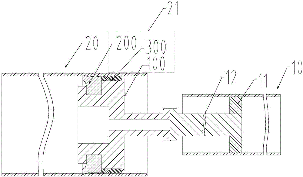
[0021] like figure 1 As shown in FIG. 1 , it is a structural schematic diagram of the application of the concrete piston of the present invention to a traditional pumping system. The pumping system includes a master cylinder 10 and a delivery cylinder 20 . Wherein, the master oil cylinder 10 is provided with a master oil cylinder piston 11 and a master oil cylinder piston rod 12 connected with the master oil cylinder piston 11 . The delivery cylinder 20 is provided with a concrete piston 21 based on the present invention, and the concrete piston 21 is connected with the piston rod 12...


PUM


Abstract

The invention discloses a concrete piston, a pumping system and a concrete pump. The concrete piston comprises a piston body, a seal body and a guide ring, wherein the seal body and the guide ring are arranged at the front end and the back end of the piston body in the circumferential direction correspondingly. The concrete piston is characterized in that the seal body or/and the guide ring is/and further embedded with solid lubricant. Because the seal body or/and the guide ring is/and further embedded with the solid lubricant, the self-lubricating effect can be achieved, a solid lubrication film is formed between friction contact faces, and direct contact and friction between the friction faces are reduced; and in this way, the friction loss among the seal body and the guide ring of the concrete piston and a conveying cylinder can be lowered without the dependence on external supply, and the service lives of the concrete piston and the conveying cylinder are prolonged. When inputting of external lubricating grease is discontinuous or interrupted, a good lubricating effect is still kept, and the non-lubrication working condition and the dry friction working condition are avoided. Besides, automatic and continuous feeding of the external lubricating grease can be changed to manual and intermittent feeding, the use cost is lowered, and lubricating configuration is simplified.

Description

technical field [0001] The invention relates to the field of concrete pump machinery, in particular to a concrete piston, a pumping system and a concrete pump. Background technique [0002] During the working process of the concrete delivery pump, there will be continuous reciprocating relative motion between the concrete piston and the delivery cylinder, resulting in direct contact between the sealing body and the guide ring of the concrete piston and the inner wall of the delivery cylinder, resulting in friction and wear. When the wear accumulates to a certain extent, Then the problem of slurry leakage or even complete failure may occur. Therefore, in order to reduce the occurrence of wear between the sealing body of the concrete piston, the guide ring and the inner wall of the delivery cylinder, it is necessary to ensure a good lubrication effect between the concrete piston and the delivery cylinder. [0003] In the prior art, one is to intermittently input lubricating o...

Claims


Application Information

Patent Timeline
Patent Type & Authority Applications(China)
IPC IPC(8): F04B53/14F04B53/18F04B15/02
CPCF04B53/14F04B15/02F04B53/143F04B53/18
Inventor 唐宜欧耀辉姜辉
Owner SANY AUTOMOBILE MFG CO LTD
Why Eureka
Try Eureka