Encoder

An encoder and compensation voltage technology, applied in the encoder field, can solve problems such as not considering temperature characteristics, time-consuming, temperature distribution errors, etc.

Active Publication Date: 2017-03-08
SANKYO SEIKI MFG CO LTD
View PDF9 Cites 2 Cited by
  • Summary
  • Abstract
  • Description
  • Claims
  • Application Information

AI Technical Summary

Problems solved by technology

[0008] However, in the technique disclosed in Patent Document 1, temperature control is performed using a heater pattern and the MR element is kept at a constant temperature, but there are following problems: (1) It takes time until the temperature of the MR element becomes constant at startup , (2) Due to the different positions of the temperature sensor and the magnetic sensitive film, the temperature inside the chip is different, and it is easy to cause errors due to the temperature distribution. (3) In order to cope with the change of the compensation voltage over time, use the The compensation voltage of the MR element is used as the compensation voltage of the MR element at startup, but this does not consider the temperature characteristics

Method used


Image

  • Encoder
  • Encoder
  • Encoder

Examples


no. 1 approach >

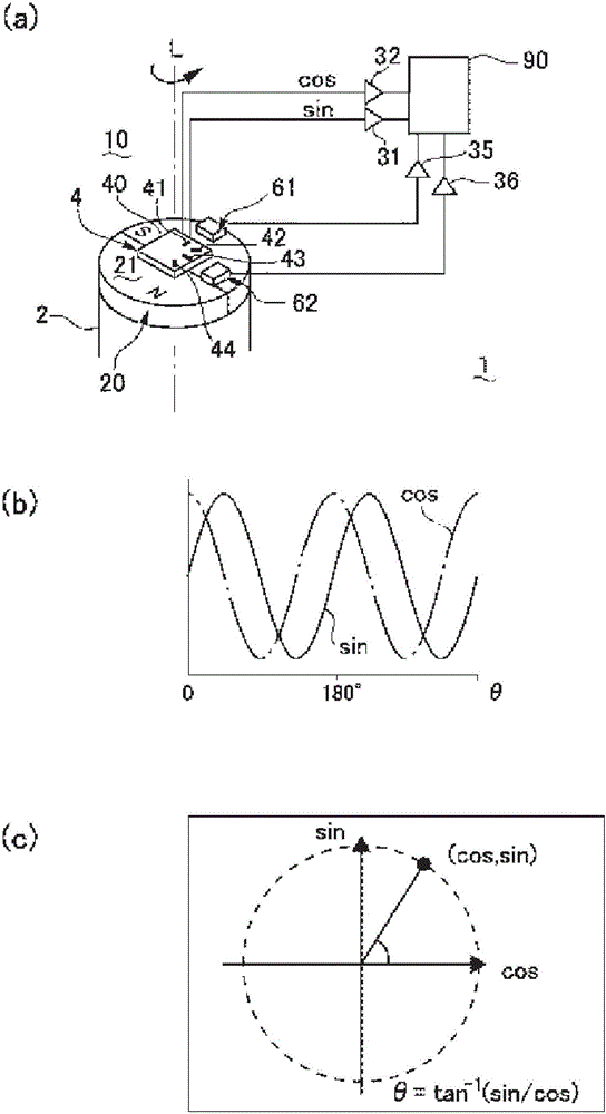
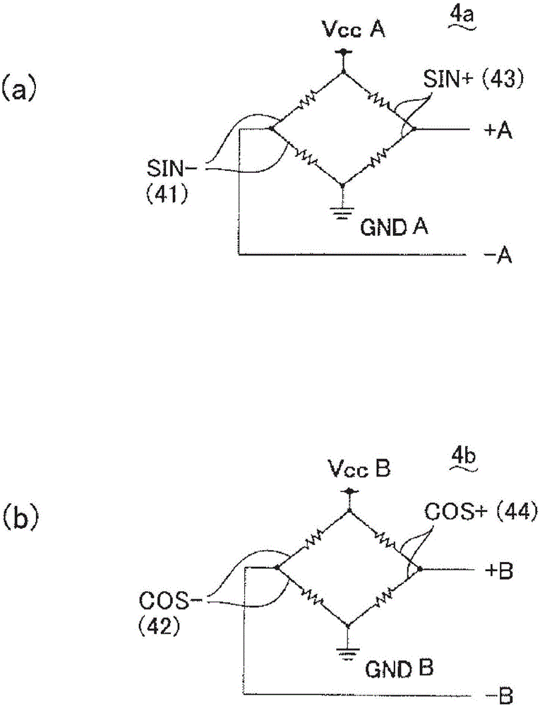
[0028] figure 1 It is an explanatory diagram showing the principle of the magnetic sensor device 10 and the rotary encoder 1 according to the first embodiment of the present invention. figure 1 (a) is a figure explaining the signal processing system with respect to the magnetic sensitive element 4 etc. FIG. figure 1 (b) is a figure explaining the signal output from the magnetic induction element 4. figure 1 (c) is a diagram showing the relationship between the signal and the angular position (electrical angle) of the rotating body 2 . figure 2 It is a diagram explaining the electrical connection structure of the magnetic sensitive films 41 to 44 (magnetoresistive films) used in the magnetic sensor device 10 and the magnetic sensitive element 4 of the rotary encoder 1 . figure 2 (a) The figure which shows the bridge circuit 4a which consists of the magnetic-sensitive film 43 of +A phase, and the magnetic-sensitive film 41 of -A phase. figure 2 (b) is a figure which shows ...

no. 2 approach >

[0064]In this embodiment, the temperature of the magnetic sensing element itself is directly detected based on the current flowing through the magnetic sensing element (MR element), and a compensation voltage for the temperature is calculated. In addition, the structure other than the temperature measurement technology of the magnetic sensitive element (MR element) can be realized by the same structure and function as the first embodiment, so the characteristic technology in this embodiment will be described, and the same structure and function will be marked the same symbol and omit its description.

[0065] Figure 6 It is a diagram explaining the electrical connection structure of the magnetic sensitive films 41 to 44 (magnetoresistive films) used in the magnetic sensor device 10 and the magnetic sensitive element 4 of the rotary encoder 1 . Here, the bridge circuit 4a on the A-phase side is shown, which is the bridge circuit 4a in the first embodiment. figure 2 The conf...


PUM


Abstract

The present invention provides an encoder capable of reducing the influence of the temperature characteristic of the magnetoresistive element on the compensation voltage. In the operation of the encoder, the compensation adjustment unit (94) sequentially records the compensation voltage and the temperature of the magneto-sensitive element in the storage unit (95). The compensation adjustment unit (94) calculates an approximate expression based on the data of the storage unit (95), thereby calculating the temperature characteristic of the compensation voltage. The compensation adjustment unit (94) calculates the compensation voltage immediately after the start of the start, starting from the detection result and the temperature characteristic of the temperature monitoring resistor film and the temperature calculation unit (93) when the encoder is started next time.

Description

technical field [0001] The invention relates to an encoder, in particular to an encoder with a magnetic sensor arrangement. Background technique [0002] An encoder for detecting rotation of a rotating body includes, for example, a magnetic sensor device in which a magnet is provided on the rotating body side and a magnetoresistive element (hereinafter referred to as "MR element") or a Hall element is provided on the fixed body side. In this magnetic sensor device, a magnetically sensitive film made of a magnetoresistive film is formed on one surface of a substrate, and based on an output from a bridge circuit of two phases (A phase and B phase) made of the magnetically sensitive film, a rotating body is detected. angular velocity or angular position, etc. [0003] Here, in general, the resistance value of a magnetic sensitive film used for an MR element or a Hall element used in a magnetic sensor device changes with temperature. Therefore, there has been proposed a techni...

Claims


Application Information

Patent Timeline
Patent Type & Authority Applications(China)
IPC IPC(8): G01D5/16
CPCG01D5/16G01D5/244G01R33/0017G01R33/09H02K11/215
Inventor 奥村宏克斋藤丰
Owner SANKYO SEIKI MFG CO LTD
Why Eureka
Try Eureka