Pressure turbine and movable guide vane of same and air-compensating hole designing method for same

A technology of movable guide vanes and design methods, which is applied in the direction of reaction engines, mechanical equipment, machines/engines, etc., can solve the problems of difficult processing, poor anti-cavitation effect, unreasonable design of anti-cavitation and air supply structure, etc., and achieve easy operation , Accurate gas concentration, and the effect of reducing the degree of cavitation damage

Active Publication Date: 2017-03-08
XIHUA UNIV
View PDF5 Cites 4 Cited by
  • Summary
  • Abstract
  • Description
  • Claims
  • Application Information

AI Technical Summary

Problems solved by technology

[0008] In view of this, the first object of the present invention is to provide a method for designing the air supply hole of the movable guide vane of the impact turbine, which can effectively solve the unreasonable design of the existing anti-cavitation structure of the impact turbine , resulting in technical problems such as difficult processing and poor anti-cavitation effect, the second purpose of the present invention is to provide a movable guide vane of the impact water turbine designed by the design method of the above air supply hole, the third purpose of the present invention is to provide An impact water turbine comprising the movable guide vanes of the above impact water turbine

Method used


Image

  • Pressure turbine and movable guide vane of same and air-compensating hole designing method for same
  • Pressure turbine and movable guide vane of same and air-compensating hole designing method for same
  • Pressure turbine and movable guide vane of same and air-compensating hole designing method for same

Examples


Embodiment Construction

[0058] The embodiment of the invention discloses a method for designing the air supply hole of the movable guide vane of the impact water turbine, so as to solve the technical problems such as unreasonable design of the anti-cavitation air supply structure of the existing impact water turbine, resulting in difficult processing and poor anti-cavitation effect.

[0059] The following will clearly and completely describe the technical solutions in the embodiments of the present invention with reference to the accompanying drawings in the embodiments of the present invention. Obviously, the described embodiments are only some, not all, embodiments of the present invention. Based on the embodiments of the present invention, all other embodiments obtained by persons of ordinary skill in the art without making creative efforts belong to the protection scope of the present invention.

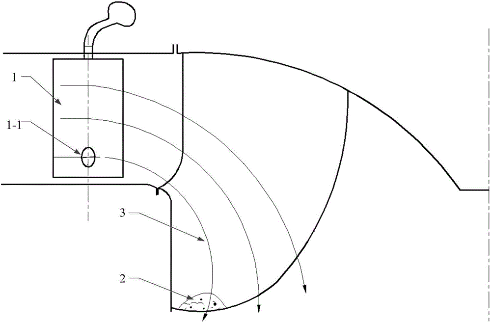
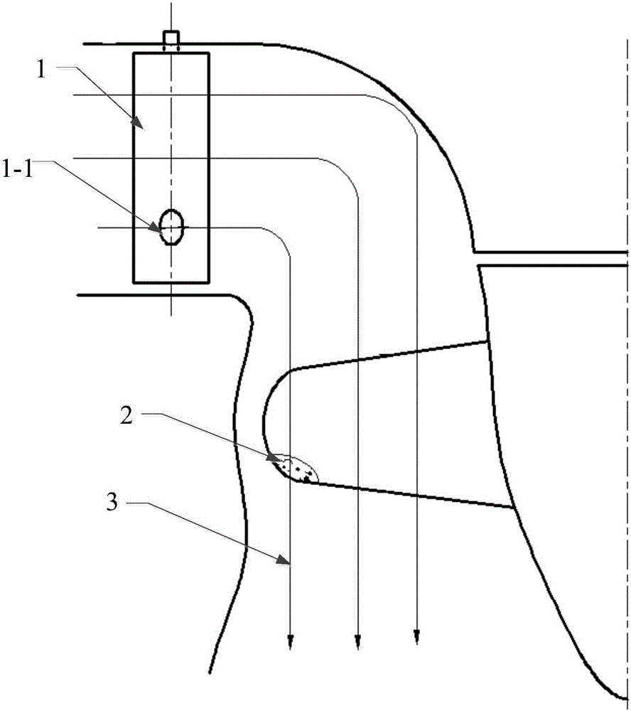
[0060] see Figure 1-Figure 3 , figure 1 It is a schematic flow diagram of the design method of the...


PUM


Abstract

The invention discloses an air-compensating hole designing method for a movable guide vane of a pressure turbine, and a pressure turbine and a movable guide vane. The air-compensating hole designing method comprises steps of building a full-simulation mathematic model for the movable guide vane of the turbine and a rotating wheel, carrying out mesh generation for the mathematic models of the movable guide vane and the rotating wheel, introducing well-divided grids of hydrodynamics calculation software to achieve a calculation result of flow characteristic of a solution domain, analyzing pressure distribution of the calculation result to determine an air-compensating hole position of the movable guide vane, primarily setting a size of the air-compensating hole based on an analysis of the calculation result, an simulating erosion reducing effect of the air-compensating hole to achieve the size of the air-compensating hole. According to empirical formula conclusion, air-compensating hole air entrainment concentration can be precisely controlled, so cavitation corrosion destroying degree of the interior of the pressure turbine rotating wheel can be effectively reduced; and problems of irrational design of the turbine anti-cavitation corrosion air-compensating structure, difficult processing and poor anti-cavitation corrosion effect can be solved.

Description

technical field [0001] The present invention relates to the technical field of hydropower equipment, and more specifically, relates to a method for designing an air supply hole of a movable guide vane of an impact water turbine, a movable guide vane of an impact water turbine, and an impact water turbine. Background technique [0002] Hydroelectric power generation means that the water flow through the water turbine converts its own potential energy and kinetic energy into rotational mechanical energy, which drives the generator to rotate, thereby converting water energy into electrical energy. Among them, the impact water turbine is the most widely used water turbine at present, mainly including Francis water turbines. There are two types of axial flow turbines. [0003] The runner of the water turbine is the main part of energy conversion. When the pressure at a certain point on the runner blade drops to the vaporization pressure at the current liquid temperature, airfoil ...

Claims


Application Information

Patent Timeline
Patent Type & Authority Applications(China)
IPC IPC(8): G06F17/50F03B3/06F03B3/14
CPCF03B3/06F03B3/14G06F30/17G06F30/18G06F30/23Y02E10/20
Inventor 曾永忠刘小兵宋占宽佘瑶
Owner XIHUA UNIV
Why Eureka
Try Eureka