Decoupling microstrip array antenna

A microstrip array and decoupling technology, applied in the directions of antenna, antenna coupling, antenna array, etc., can solve the problems of increased side lobe level of the array antenna pattern, coupling interference of radar transceiver antenna, and failure to work normally, and achieves easy operation. Carrier conformal, high gain, high isolation effect

Active Publication Date: 2017-03-08
SHANGHAI SUSR TELECOM TECH
View PDF4 Cites 7 Cited by
  • Summary
  • Abstract
  • Description
  • Claims
  • Application Information

AI Technical Summary

Problems solved by technology

[0006] The present invention aims to solve the problem that the microstrip array antenna is seriously coupled, which leads to the increase of the side lobe level of the array antenna pattern, the decrease of the gain, and the problem that the coupling interference of the radar transceiver antenna cannot work normally.

Method used


Image

  • Decoupling microstrip array antenna
  • Decoupling microstrip array antenna

Examples


Embodiment Construction

[0021] Below in conjunction with specific embodiment, further illustrate the present invention. It should be understood that these examples are only used to illustrate the present invention and are not intended to limit the scope of the present invention. In addition, it should be understood that after reading the teachings of the present invention, those skilled in the art can make various changes or modifications to the present invention, and these equivalent forms also fall within the scope defined by the appended claims of the present application.

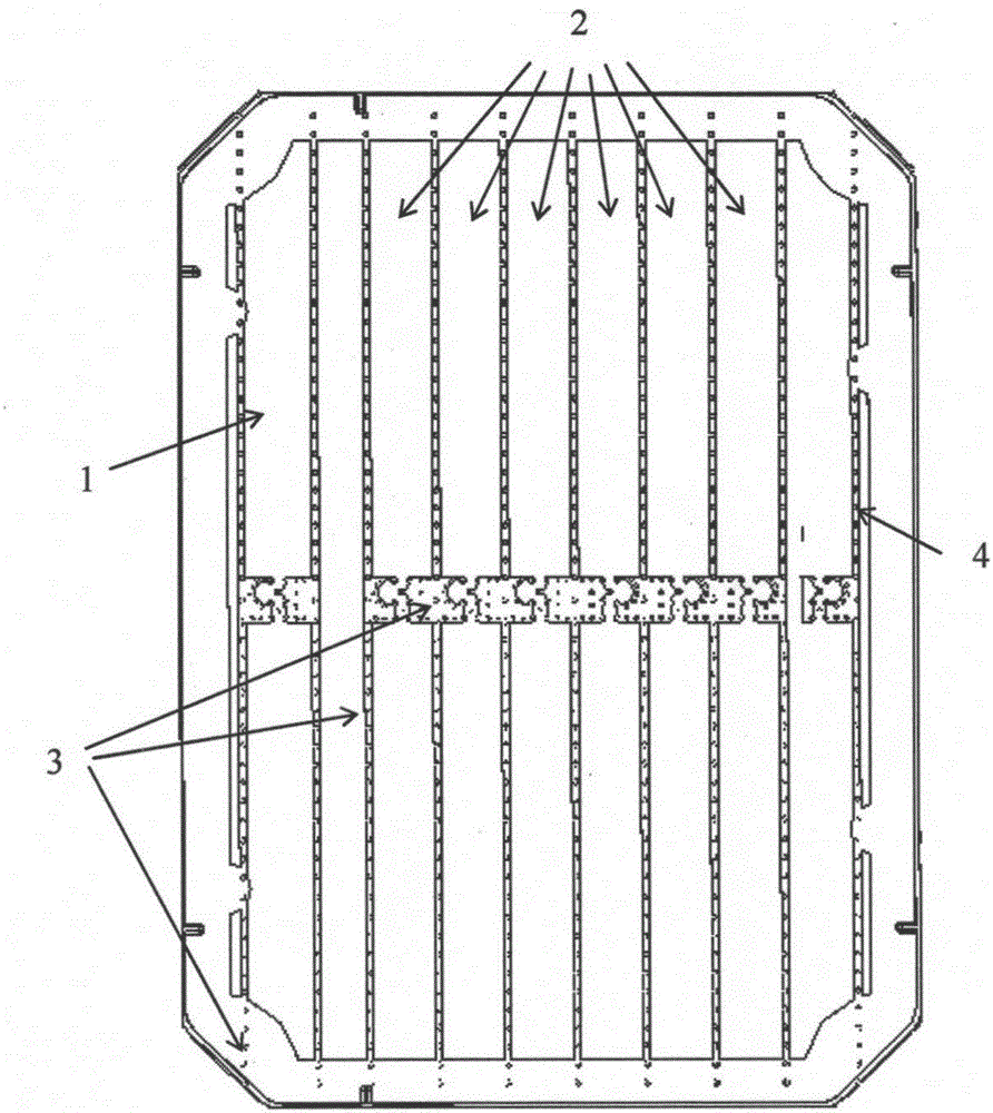
[0022] figure 1 The front plan view of the decoupling microstrip array antenna provided in this embodiment, the decoupling microstrip array antenna is mainly composed of a microstrip dielectric plate, an antenna radiator, metallized via holes and a transmission line grid. The antenna radiator includes a serial fed receiving antenna array and a serial fed transmitting antenna array.

[0023] A serial fed receiving antenna arra...


PUM


Abstract

The invention provides a decoupling microstrip array antenna. The decoupling microstrip array antenna comprises a microstrip dielectric plate, wherein multiple groups of microstrip arrays are arranged on the microstrip dielectric plate, the microstrip arrays are formed by connecting a plurality of microstrip patch units in series, a transmission line lattice network is arranged between adjacent groups of microstrip arrays, metal via holes are further informed in the microstrip dielectric plate, the transmission line lattice network communicates with a metal grounding layer through the metal via holes, and a feeding network communicates with a back surface of the microstrip dielectric plate through the metal via holes. In the decoupling microstrip array antenna provided by the invention, the coupling interference between array antennas is substantially reduced with the adoption of the metal via holes and transmission line lattices, and the decoupling microstrip array antenna has the advantages of high isolation, miniaturization, low profile, high grain and easiness in carrier conformality, and can be applied to the technical field of radar, remote sensing, electronic countermeasure and wireless communication systems.

Description

technical field [0001] The invention relates to an antenna, in particular to a decoupling microstrip array antenna. Background technique [0002] The microstrip antenna has the characteristics of small size, light weight, low profile, easy installation and conformal with the carrier surface, and the feed network can be made together with the antenna, which is suitable for mass production with printed circuit technology and low cost; Integrate the antenna with active devices or circuits to realize a fully integrated transceiver front-end module. Therefore, microstrip antenna technology has received widespread attention and has been widely used in millimeter wave radar, communication, guidance and other fields. At present, with the improvement of production technology, the discovery of new materials, and the continuous improvement and deepening of material processing technology, high-gain, easy-to-integrate antenna arrays have increasingly become the focus of research. [00...

Claims


Application Information

Patent Timeline
Patent Type & Authority Applications(China)
IPC IPC(8): H01Q1/52H01Q21/00
CPCH01Q1/523H01Q21/0006
Inventor 李振华谢倩倩
Owner SHANGHAI SUSR TELECOM TECH
Why Eureka
Try Eureka