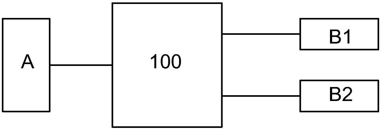
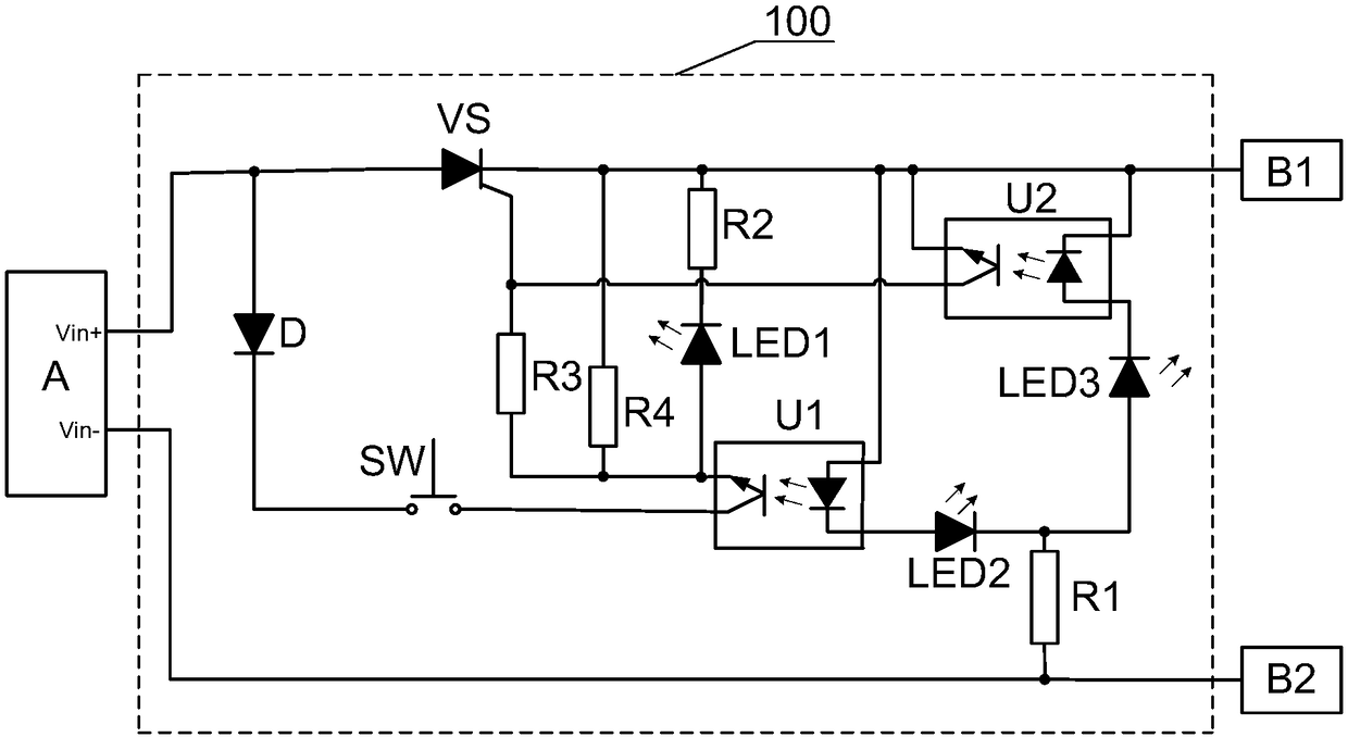
[0002] With the progress of society, more and more people own private cars, but improper use often leads to many problems, such as forgetting to turn off the car lights when leaving, or forgetting to turn off the on-board
electronic equipment. It is easy to have insufficient power, and when starting the vehicle next time, the power used is also provided by the battery. When the battery power is insufficient, the car will fail to start. Start to provide power
However, because both the car battery (vehicle battery) and the emergency start power supply have the characteristics of generating instantaneous large current, if the emergency start power supply is used as the car start power supply, if a
short circuit or
reverse connection occurs due to
carelessness, an upper current may be generated instantaneously. The
high current of 1,000 amperes will not only cause damage to the emergency starting power supply, but may even cause a fire or
cause injury to the user.
[0003] For this reason, many manufacturers have begun to study anti-
reverse connection and short-circuit circuits on the emergency starting power supply of automobiles. For example, the
patent application number is: 200520054634.1 discloses a multifunctional starting power supply for automobiles. The anti-reverse connection short-
circuit protection circuit connected between the relays controls the current path specifically. As we all know, the emergency starting power supply and the vehicle-mounted battery have the characteristics of generating instantaneous large currents, so the
relay must use a large
relay, so there is an anti-
corrosion protection circuit composed of relays. The defect that the reverse connection
short circuit protection circuit is relatively bulky; because the current path is opened immediately when the battery on the vehicle is correctly connected, there is a defect that ignition occurs when the battery is clipped to the battery on the vehicle, although there is a light
touch switch to start The emergency starting power supply is only used for removing the battery on the vehicle; in order to disconnect the emergency starting power supply to the current path of the battery clamp after taking out the battery clip from the working point of the vehicle, there are respectively set on the inside of the upper and lower splints of the battery clamp Usually do not touch each other, and lead wires to the anti-reverse short-
circuit protection circuit separately, so there is a defect that the battery clip cannot use a
single lead wire to the anti-reverse short-circuit protection circuit
[0004] Nowadays, the advancement of buried batteries has led to its wide-scale use. Using buried batteries as emergency start-up power has become a common practice in the industry, and the anti-reverse short-circuit protection circuit that uses relays to form the current path of emergency start-up power is too bulky and cumbersome. The emergency start power is often used as a 12V18AH lead-acid maintenance-free battery. The whole
system weighs about 10 kg, so the problem of portability cannot be considered. However, when the emergency start power is replaced with a buried battery, the weight of the whole
system is only 400 grams. The volume and weight of the anti-reverse connection short-circuit protection circuit that constitutes the current path of the emergency starting power supply are obviously not suitable.
Therefore, there is an anti-reverse short-circuit protection circuit that uses
semiconductor devices to form the current path of the emergency start-up power supply. For example, a
patent application number: 201410399268.7 discloses an emergency power supply short-circuit protection system. The anti-reverse short-circuit protection circuit uses
field effect tubes to control the current path, which overcomes the relatively bulky defect of the anti-reverse short-circuit protection circuit composed of relays, but there are still: because the current path is immediately opened when the battery on the vehicle is correctly connected, Therefore, there is a defect that the battery clip is caught in the process of clamping the battery on the vehicle; in order to disconnect the emergency starting power supply to the current path of the battery clip after taking out the battery clip from the vehicle's working point, two splints on the upper and lower sides of the battery clip There are points on the inner side that are not in contact with each other at ordinary times, and lead wires to the anti-reverse short-circuit protection circuit, so there is a defect that the battery clip cannot use a
single lead wire to the anti-reverse short-circuit protection circuit
Another example is the
patent application number: 201520322213.6, which discloses an emergency power supply anti-short-circuit protection system, which can be read in conjunction with the practical drawings: the anti-reverse connection short-circuit protection circuit connected between the emergency start power supply and the vehicle-mounted battery (spare battery) In this way, the
field effect tube is used to control the current path, which overcomes the cumbersome defect of the anti-reverse short-circuit protection circuit formed by the
relay; The defect that the battery clip is caught in the process of clamping the battery on the car is sparking. Although there is a light
touch switch to start the emergency power supply, it is only used to remove the battery on the car; in order to remove the battery clip from the working point of the car Disconnect the emergency starting power supply to the current path of the battery clip. There are points not in contact with each other on the inner side of the upper and lower splints of the battery clip, and lead wires to the anti-reverse short-circuit protection circuit respectively. Therefore, there is a battery clip that cannot be connected with a single lead wire. Defects of anti-reverse connection short-circuit protection circuit; there is another serious defect of this utility: if the emergency start power supply is reversed, it may cause damage to the
comparator Login to View More

