Circuit applied to negative ion air cleaner

An air purifier and negative ion technology, applied in the field of air purification, can solve problems such as dust and poor movement, and achieve the effects of lower price, convenient use, and scientific and reasonable design.

Inactive Publication Date: 2017-03-15
重庆依凯科技有限公司
View PDF8 Cites 2 Cited by
  • Summary
  • Abstract
  • Description
  • Claims
  • Application Information

AI Technical Summary

Problems solved by technology

[0019] Second, poor

Method used


Image

  • Circuit applied to negative ion air cleaner
  • Circuit applied to negative ion air cleaner
  • Circuit applied to negative ion air cleaner

Examples


Embodiment 1

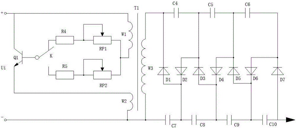
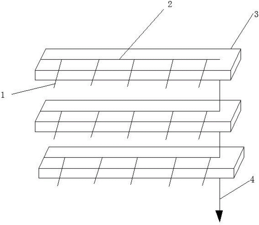
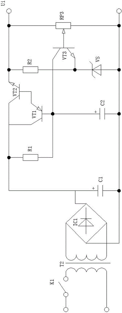
[0045] The circuit applied to the negative ion air purifier is based on the voltage doubler rectifier circuit, inductive oscillator, DC power supply and discharge components, using the resistor R1, the resistor R2, the potentiometer RP3, the capacitor C2, the voltage regulator VS, the triode VT1 and the triode The voltage stabilization comparator circuit composed of VT2 performs the power supply voltage stabilization processing after the output of the voltage variable rectification circuit, obtains a stable DC output and supplies it to the subsequent stage circuit, and provides a highly reliable voltage for the safe and stable operation of the latter stage circuit, so that safe and reliable operation of the entire circuit, such as figure 1 , figure 2 , image 3 As shown, the following configuration structure is particularly adopted: a voltage doubler rectifier circuit, an inductive oscillator, a DC power supply and a discharge component are provided, the inductive oscillator...

Embodiment 2

[0047] This embodiment is further optimized on the basis of the above-mentioned embodiments. Further, in order to better realize the present invention, bridge rectification can be used to rectify the AC power after structural transformation, and then use the filter capacitor to filter out the contained Ripple voltage, and the voltage regulation comparator circuit is used to stabilize the output, to provide a safe and reliable DC voltage for the subsequent stage, such as figure 1 , figure 2 , image 3 As shown, the following arrangement structure is particularly adopted: a switch K1, a power transformer T2, a bridge rectifier stack IC1 and a filter capacitor C1 are arranged in the voltage-changing rectifier circuit, and the switch K1 is arranged at one end of the primary end of the transformer power transformer T2 Above, the secondary end of the power transformer T2 is connected to the input end of the bridge rectifier stack IC1, and the output end of the bridge rectifier sta...

Embodiment 3

[0049] This embodiment is further optimized on the basis of any of the above embodiments, further to better realize the present invention, such as figure 1 , figure 2 , image 3 As shown, the following arrangement structure is particularly adopted: the capacitor C1 is a filter capacitor, and the anode of the capacitor C1 is connected to the first end of the resistor R1.


PUM


Abstract

The invention discloses a circuit applied to a negative ion air cleaner. The circuit is provided with a voltage doubling rectifying circuit, an inductive oscillator, a direct-current power supply and a discharging component, wherein the inductive oscillator is connected with the voltage doubling rectifying circuit; the voltage doubling rectifying circuit is connected with the discharging component; and a voltage transformation rectifying circuit, a resistor R1, a resistor R2, a potentiometer RP3, a capacitor C2, a voltage-regulator tube VS, a triode VT1 and a triode VT2 are arranged inside the direct-current power supply. Based on the voltage doubling rectifying circuit, the inductive oscillator, the direct-current power supply and the discharging component, a voltage stabilization comparison circuit composed of the resistor R1, the resistor R2, the potentiometer RP3, the capacitor C2, the voltage-regulator tube VS, the triode VT1 and the triode VT2 is utilized for power supply voltage stabilization treatment after output of the voltage transformation rectifying circuit so that direct-current output with good stability is obtained and supplied to a post-stage circuit and voltage with high reliability is provided for safe and stable running of the post-stage circuit, and thus the overall circuit can run safely and reliably.

Description

technical field [0001] The invention relates to the fields of air purification and the like, in particular to a circuit applied to negative ion air purifiers. Background technique [0002] Smog, as the name suggests, is fog and haze. But the difference between fog and haze is very big. The aerosol system composed of dust, sulfuric acid, nitric acid and other particles in the air causes visual impairment called haze. Haze is haze (haze). [0003] Fog is an aerosol system composed of a large number of tiny water droplets or ice crystals suspended in the air near the surface. It mostly occurs in autumn and winter, and is the product of condensation (or sublimation) of water vapor in the air near the surface. The existence of fog will reduce the transparency of the air and deteriorate the visibility. If the horizontal visibility of the target is reduced to within 1000 meters, the weather phenomenon of water vapor condensation (or sublimation) suspended in the air near the su...

Claims


Application Information

Patent Timeline
IPC IPC(8): B03C3/66H02M7/217H02M3/335H02M7/48
CPCB03C3/66H02M3/33523H02M7/217H02M7/48H02M7/4815Y02B70/10
Inventor 李建忠
Owner 重庆依凯科技有限公司
Why Eureka
Try Eureka