
Mechanical processing equipment capable of realizing any-angle cutting

A mechanical processing and arbitrary angle technology, applied in metal processing equipment, welding/cutting auxiliary equipment, welding equipment, etc., can solve problems such as stability and accuracy defects, increase production costs, and workpiece quality limitations, and achieve simple structure , stable operation, and the effect of reducing production costs

Active Publication Date: 2017-03-15
江苏汉达机械有限公司
View PDF7 Cites 37 Cited by
  • Summary
  • Abstract
  • Description
  • Claims
  • Application Information

AI Technical Summary

Problems solved by technology

[0003] In order to improve production efficiency and reduce labor costs, many companies use automated cutting robots for cutting operations. However, most of the existing cutting robots use oil cylinders, cylinders, and motor gears as power for expansion and rotation. This form of drive has advantages in stability and There are defects in accuracy, which will limit the quality of the processed workpieces. At the same time, for existing workpieces, the cutting angle is very important. The required angle can be cut at one time, which will greatly reduce the production cost.
[0004] When a cutting or welding robot (application number 201110033209.4) of the Chinese patent is in use, the requirement for the cutting angle can only ensure that the cutting angle is vertical. For the current parts processing requirements, this technology has been difficult to meet the current needs, which is also The common problems of existing cutting machines, the existing methods are secondary or even multiple processing, which will greatly increase the production cost

Method used


Image

  • Mechanical processing equipment capable of realizing any-angle cutting
  • Mechanical processing equipment capable of realizing any-angle cutting
  • Mechanical processing equipment capable of realizing any-angle cutting

Examples


Embodiment Construction

[0032] In order to make the object, technical solution and advantages of the present invention clearer, the present invention will be further described in detail below in conjunction with the accompanying drawings and embodiments. It should be understood that the specific embodiments described here are only used to explain the present invention, not to limit the present invention.

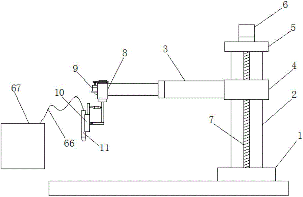
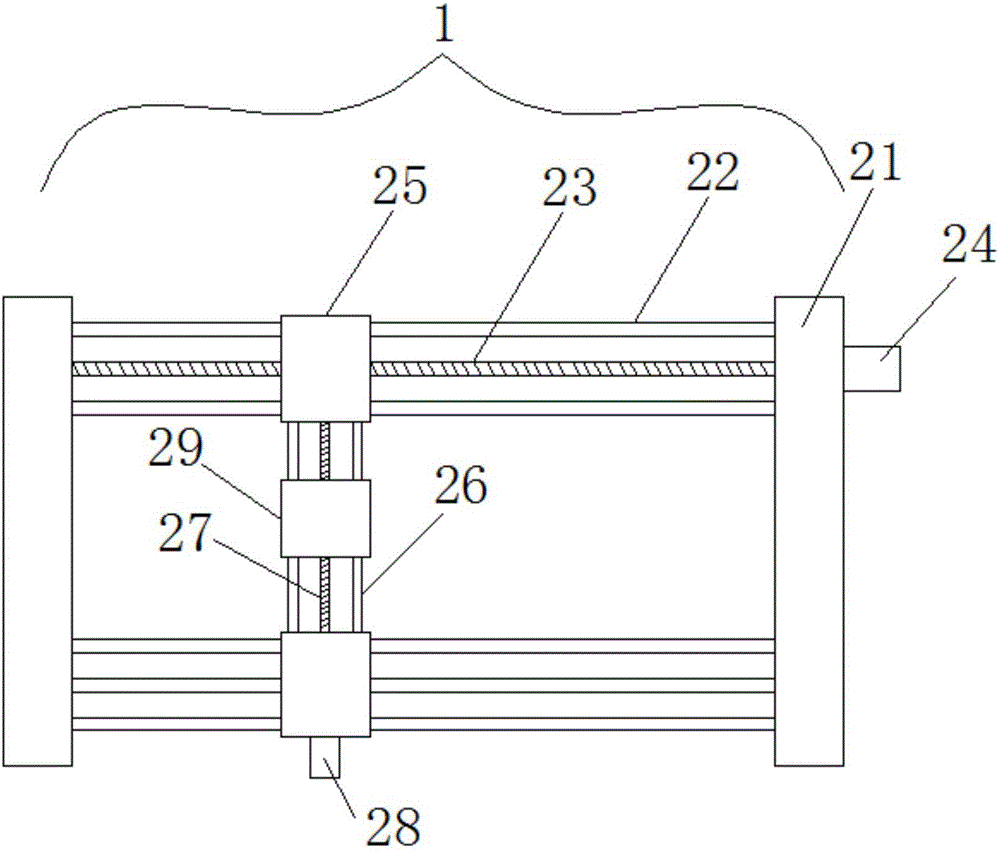
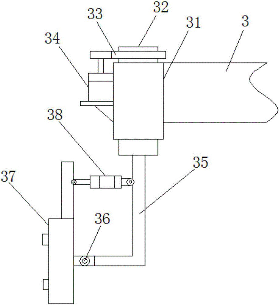
[0033] Such as figure 1 A mechanical processing equipment capable of cutting at any angle is shown, including a frame, a mobile support 1, a vertical frame 2, a beam 3, a sliding sleeve 4, a mounting plate 5, a lifting motor 6, a lifting screw 7, a cutting Head 8, the mobile support 1 is installed on the frame, the vertical frame 2 is vertically welded on the mobile support 1, and the vertical frame 2 is provided with a chute, the sliding sleeve 4 Slidingly connected to the vertical frame 2 through a chute, and the sliding sleeve 4 is provided with a threaded hole along the vertical direction, the...


PUM


Abstract

The invention discloses mechanical processing equipment capable of realizing any-angle cutting. The mechanical processing equipment comprises a movable supporting base, a vertical frame, a beam, a slide sleeve, a mounting plate, a lifting motor, a lifting lead screw and a cutting head, wherein the movable supporting base is mounted on the rack; the vertical frame is vertically welded on the movable supporting base; a slide slot is formed in the vertical frame; the slide sleeve is in sliding connection on the vertical frame through the slide slot; a threaded hole in the vertical direction is formed in the slide sleeve; the beam is horizontally welded at one side of the slide sleeve; the mounting plate is fixedly connected on the top of the vertical frame; the upper end and the lower end of the lifting lead screw are separately connected on the mounting plate and the movable supporting base through bearing bases; the lifting lead screw is connected with the slide sleeve through threads; the lifting motor is fixedly connected on the mounting plate; the output shaft of the lifting motor is fixedly connected with the lifting lead screw; and the cutting head is mounted at the top end of the beam. The mechanical processing equipment has the advantages of being simple in structure, stable in operation, high in precision, capable of reducing production cost and the like.

Description

technical field [0001] The invention relates to the technical field of machine cutting equipment, in particular to a mechanical processing equipment capable of cutting at any angle. Background technique [0002] Plasma cutting with different working gases can cut all kinds of metals that are difficult to cut by oxygen cutting, especially for non-ferrous metals (stainless steel, aluminum, copper, titanium, nickel). Its main advantage is that it can cut metals with small thickness. At present, the plasma cutting speed is fast, especially when cutting ordinary carbon steel sheets, the speed can reach 5-6 times that of the oxygen cutting method, the cutting surface is smooth, the thermal deformation is small, and the heat-affected zone is less. Plasma cutting machines are widely used in various industries such as automobiles, locomotives, pressure vessels, chemical machinery, nuclear industry, general machinery, engineering machinery, steel structures, and ships. [0003] In or...

Claims


Application Information

Patent Timeline
IPC IPC(8): B23K10/00B23K37/02
CPCB23K10/00B23K37/0252
Inventor 梁季
Owner 江苏汉达机械有限公司
Learn More