Intelligent injection allocation device of integrated electromagnetic flowmeter
An integrated electromagnetic and flow meter technology, applied in the direction of measurement, production fluid, wellbore/well components, etc., can solve the problems of low qualification rate of layered water injection, heavy manual work, and inability to realize real-time monitoring downhole, etc., to reduce The risk of encountering obstacles and getting stuck, high test accuracy, and the effect of improving test accuracy
- Summary
- Abstract
- Description
- Claims
- Application Information
AI Technical Summary
Problems solved by technology
Method used
Image

Examples
Embodiment 1
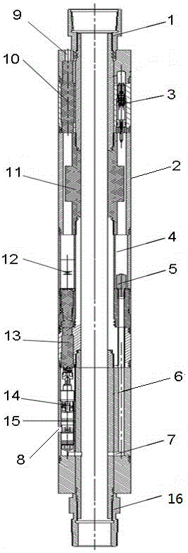
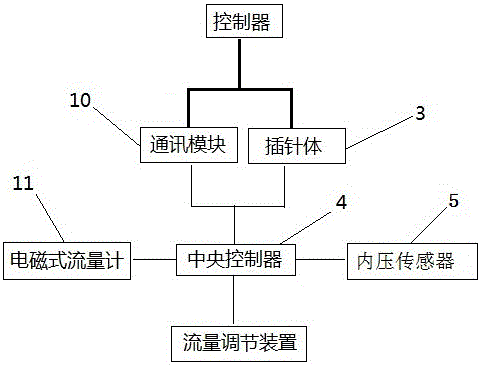
[0026] Such as figure 1 with figure 2 As shown, the present invention provides an integrated electromagnetic flowmeter intelligent dispenser, which includes an upper joint 1, a housing 2 and a lower joint 16 connected sequentially from top to bottom, and the pipe wall of the housing 2 Set as an annular cavity, the lower part of the casing 2 is provided with a water outlet 8, and the interior of the dispenser is arranged as a hollow channel along the axial direction, and the feature is that a central controller 4 is installed in the middle of the annular cavity of the casing 2 , the annular cavity above the central controller 4 is equipped with an electromagnetic flowmeter 11, the communication module 10 and the pin body 3 are installed in the annular cavity above the electromagnetic flowmeter 11, and the annular cavity at the lower part of the central controller 4 A flow regulating device and an internal pressure sensor 5 are installed in the cavity, and the central controll...
Embodiment 2
[0034] Such as figure 1 As shown, the flow regulating device is located in the lower part of the annular cavity, and includes a motor 12, a transmission coupling shaft 13, and a flow regulating plug 15 connected in sequence. The lower part of the flow regulating plug 15 is provided with a nozzle hole, and the water The mouth hole corresponds to the water outlet hole 8 outside the intelligent dispenser.
[0035] Water enters the intelligent dispenser from the oil pipe. When the nozzle hole corresponds to the water outlet hole 8 outside the intelligent dispenser, a water injection channel is formed. Water is injected into the bottom layer from the water injection channel. When the computer on the ground monitors that the flow rate is too large At this time, the data is automatically fed back to the central controller 4, thereby controlling the motor 12 to drive the transmission coupling shaft 13 to move up and down, and at the same time the transmission coupling shaft 13 moves u...
Embodiment 3
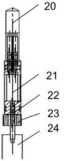
[0038] Such as Figure 4 As shown, the electromagnetic flowmeter 11 includes an outer cylinder body 17, and a hollow central tube 18 is arranged inside the outer cylinder body 17, and an induction electrode 19 is arranged radially on the side wall in the middle of the central tube 18.
[0039]When water enters the intelligent dispenser from the oil pipe, the electromagnetic flowmeter 11 located on the upper part of the intelligent dispenser measures the flow rate through the upper sensing electrode 19, the central controller 4 monitors the flow data, and transmits the data conversion through the communication module 10 to The real-time monitoring of traffic is realized on the computer.
PUM
 Abstract
Description
Claims
Application Information
 - R&D
- Intellectual Property
- Life Sciences
- Materials
- Tech Scout
- Unparalleled Data Quality
- Higher Quality Content
- 60% Fewer Hallucinations
Browse by: Latest US Patents, China's latest patents, Technical Efficacy Thesaurus, Application Domain, Technology Topic, Popular Technical Reports.
© 2025 PatSnap. All rights reserved.Legal|Privacy policy|Modern Slavery Act Transparency Statement|Sitemap|About US| Contact US: help@patsnap.com