Method for evaluating integrity of well cementing barrier

An integrity and cementing technology, applied in earthwork drilling, wellbore/well components, measurement, etc., can solve problems such as changes in the stress state of the cementing barrier system, economic losses, formation fluid in the annular space, etc., to achieve The experimental data is true and reliable, the experimental steps are clear, and the experimental principle is reliable.

Inactive Publication Date: 2017-03-15
CNOOC TIANJIN BRANCH +1
View PDF10 Cites 8 Cited by
  • Summary
  • Abstract
  • Description
  • Claims
  • Application Information

AI Technical Summary

Problems solved by technology

During the production and service of oil and gas wells, the cementing barrier is subject to various loads, such as the internal pressure transmitted through the casing, the confining pressure of the formation rock, the temperature strain caused by the temperature change of the wellbore, and the high pressure shock of the gas well. etc. During the entire life cycle of oil and gas wells, multiple loads often act and change at the same time. The action and changes of these loads will lead to changes in the stress state of the cementing barrier system, and in severe cases will cause the sealing o

Method used


Image

  • Method for evaluating integrity of well cementing barrier
  • Method for evaluating integrity of well cementing barrier
  • Method for evaluating integrity of well cementing barrier

Examples


Embodiment 1

[0038] 1. The implementation process of free casing is as follows:

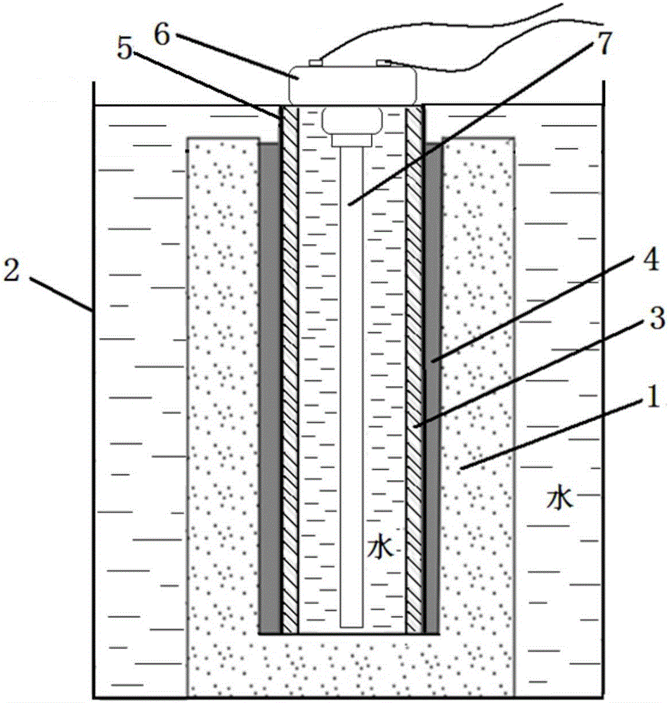
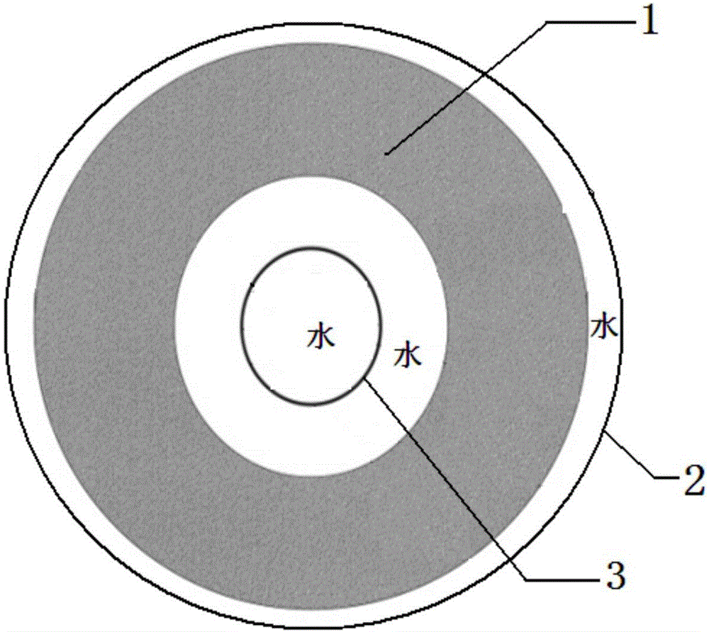
[0039] 1) A simulated formation 1 with a cylindrical structure with an open upper end and a closed lower end is produced, with a height of 1200 mm, an outer diameter of φ500 mm, and an inner diameter of φ215.9 mm.

[0040] 2) Place the prepared simulated formation 1 in the bucket 2 .

[0041] 3) Use a crane to put the casing 3 not coated with the drilling fluid layer 5 into the simulated formation 1. The outer diameter of the casing 3 is φ139.7mm, the inner diameter is φ127.6mm, and the length is 1200mm. The inserted casing 3 has a coaxial relationship with the simulated formation 1 .

[0042] 4) An ultrasonic probe 7 is fixed in the center of the casing 3 through the fixed cover 6, and the ultrasonic probe 7 is electrically connected to an external oscilloscope, a pulse generator receiver and a high-speed transient signal acquisition instrument.

[0043] 5) Water is injected into the barrel 2, the height o...

Embodiment 2

[0049] 2. When the casing 3 is only cemented with the cement sheath 4, the implementation process is as follows:

[0050] 1) A simulated formation 1 with a cylindrical structure with an open upper end and a closed lower end is produced, with a height of 1200 mm, an outer diameter of φ500 mm, and an inner diameter of φ215.9 mm.

[0051] 2) Place the prepared simulated formation 1 in the bucket 2 .

[0052] 3) Use a crane to put the casing 3 not coated with the drilling fluid layer 5 into the simulated formation 1. The outer diameter of the casing 3 is φ139.7mm, the inner diameter is φ127.6mm, and the length is 1200mm. The inserted casing 3 has a coaxial relationship with the simulated formation 1 .

[0053] 4) An ultrasonic probe 7 is fixed in the center of the casing 3 through the fixed cover 6, and the ultrasonic probe 7 is electrically connected to an external oscilloscope, a pulse generator receiver and a high-speed transient signal acquisition instrument.

[0054] 5) Wat...

Embodiment 3

[0060] 3. The cement sheath 4 is well cemented with the casing 3 and the simulated formation 1. The process is as follows:

[0061] 1) A simulated formation 1 with a cylindrical structure with an open upper end and a closed lower end is produced, with a height of 1200 mm, an outer diameter of φ500 mm, and an inner diameter of φ215.9 mm.

[0062] 2) Place the prepared simulated formation 1 in the bucket 2 .

[0063] 3) Put the casing 3 coated with the drilling fluid layer 5 into the simulated formation 1 by a crane. The outer diameter of the casing 3 is φ139.7mm, the inner diameter is φ127.6mm, and the length is 1200mm. The inserted casing 3 has a coaxial relationship with the simulated formation 1 .

[0064] 4) An ultrasonic probe 7 is fixed in the center of the casing 3 through the fixed cover 6, and the ultrasonic probe 7 is electrically connected to an external oscilloscope, a pulse generator receiver and a high-speed transient signal acquisition instrument.

[0065] 5) W...


PUM

PropertyMeasurementUnit
Outer diameteraaaaaaaaaa
The inside diameter ofaaaaaaaaaa
Outer diameteraaaaaaaaaa

Abstract

The invention relates to a method for evaluating the integrity of a well cementing barrier. The method includes the following steps that 1, a simulated formation of a tubular structure with the open upper end and the closed lower end is manufactured; 2, the manufactured simulated formation is put in a barrel; 3, a casing pipe coated with a drilling fluid layer is put in the simulated formation; 4, an ultrasonic probe is arranged in the middle in the casing pipe, and the ultrasonic probe is electrically connected with an oscilloscope, a pulse generation receiving instrument and a high-speed transient signal acquisition instrument, wherein the oscilloscope, the pulse generation receiving instrument and the high-speed transient signal acquisition instrument are arranged outside; 5, water is injected into the barrel till the water surface reaches an upper end opening of the simulated formation, and the casing pipe is filled with water; 6, cement paste is prepared; 7, the cement paste is injected between the casing pipe and the inner wall of the simulated formation, after injection is completed, water is injected into the barrel till the water surface is flush with the upper end face of the casing pipe, and waiting on cement setting is carried out; 8, the ultrasonic probe is started, the pulse generation receiving instrument is used for measuring and acquiring a well cementing acoustic amplitude curve of a to-be-measured time point, and the peak value of the first wave of the well cementing acoustic amplitude curve is read out; 9, whether the cell cementing integrity is qualified or not is judged according to the well cementing barrier integrity criterion.

Description

technical field [0001] The invention relates to a method for evaluating the integrity of a cementing barrier, belonging to the field of oil and gas exploration and development. Background technique [0002] After cementing, the casing-cement sheath-formation will form a cemented body, which plays the role of protecting the casing and supporting the formation, which is called the cementing barrier. How to improve the sealing quality of the cement sheath between the well wall and the casing is a long-term concern in cementing engineering. The mechanical properties of the cement sheath are related to the quality of the cementing barrier and the life of the oil and gas well. During the production and service of oil and gas wells, the cementing barrier is subject to various loads, such as the internal pressure transmitted through the casing, the confining pressure of the formation rock, the temperature strain caused by the temperature change of the wellbore, and the high pressure...

Claims


Application Information

Patent Timeline
IPC IPC(8): E21B47/00E21B47/14
CPCE21B47/00E21B47/14
Inventor 刘书杰许明标武治强周建良王晓亮何英明岳家平
Owner CNOOC TIANJIN BRANCH
Why Eureka
Try Eureka