
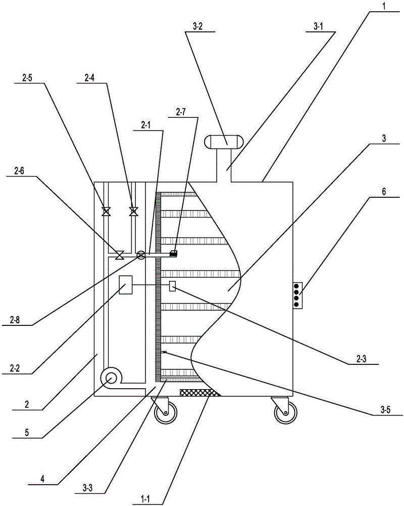
Constant-temperature type air-blowing drying oven

A blast drying oven, constant temperature technology, applied in non-progressive dryers, drying gas layout, drying and other directions, can solve problems affecting drying quality, pollution, large temperature difference, etc., to improve heat utilization rate and reasonable material setting , the effect of speeding up air circulation

Inactive Publication Date: 2017-03-15
钦州市明大检测技术有限公司
View PDF6 Cites 3 Cited by
  • Summary
  • Abstract
  • Description
  • Claims
  • Application Information

AI Technical Summary

Problems solved by technology

Although the blast drying box is simple and practical, it also faces the following problems: the interior of the blast drying box is a sealed structure, and the humidity in the box is not high at the initial stage of putting the items to be dried, so the drying effect is good
But there are still the following defects: First, because the air volume and air pressure gradually decrease during the flow process, and there is no uniformly dispersed hot air device in the working room, the direction of the heating source is single, so the temperature difference in the working room is very large, resulting in uneven drying of the samples , affect the quality of drying, and then affect the accuracy of experimental data; second, volatile substances will volatilize during the drying process, and the studio has not adopted relevant treatment devices, and the volatile substances contain acid, organic solvents, and polluting gases etc. Residues in the working room will cause cross-contamination, affect the drying quality, and be discharged into the air to cause pollution. In addition, there is no related fan on the dehumidification pipe, the air circulation rate is low, and the drying efficiency is slow

Method used


Image

  • Constant-temperature type air-blowing drying oven

Examples


Embodiment Construction

[0016] Such as figure 1 A specific embodiment of the present invention is proposed as shown, a constant temperature blast drying box, comprising a box body 1, the box body 1 is divided into a dehumidification chamber 2, a drying chamber 3 communicated with the dehumidification chamber 2 through a dehumidification pipeline 2-1, One side of the dehumidification pipeline 2-1 is provided with a discharge pipe, the discharge pipe is provided with a vent valve 2-4, and the dehumidification pipeline 2-1 also has a circulation valve 2-6, and its port is connected with a circulation pipe, One end of the circulation pipe is provided with an air inlet pipe, and the air inlet pipe is provided with an air inlet valve 2-6, and the other end of the circulation pipe is connected to the blower 5, and there is a gap between the drying chamber 3 and the inner wall of the box body 1 , form an air channel 4, the air channel 4 communicates with the blower 5 through the air pipe, a control valve 2-2...


PUM


Abstract

The invention discloses a constant-temperature type air-blowing drying oven which comprises a box body, wherein the box body is divided into a dehumidifying cavity and a drying cavity; an air runner is formed between the drying cavity and the inner wall of the box body; a control valve is arranged in the dehumidifying cavity; the control valve is connected with a temperature inductor, and is used for controlling an air release valve, an air inlet valve and a circulating valve in the dehumidifying cavity; a rotary shaft is arranged on the top of the drying cavity; a drive device is arranged on the rotary shaft; air distributing plates are arranged at the periphery of the drying cavity; and an induced draft fan is arranged on a dehumidifying tube, and the port of the induced draft fan is further connected with a wet gas purifying device which is a multi-layer net structure. The rotary shaft and the air distributing plates are additionally arranged on an existing drying oven gas circulating system to form a ventilating circulating system, so that temperature uniformity and good drying quality in a drying cavity are guaranteed; the gas in the cavity is clean, so that cross contamination is avoided; and the constant-temperature type air-blowing drying oven is high in drying rate, is good in drying quality, is high in heat utilization rate, is good in practicability and is worthy of being widely popularized.

Description

technical field [0001] The invention relates to the field of drying equipment, in particular to a constant temperature blast drying box. Background technique [0002] Blast drying oven, also known as "oven", is widely used in the drying of experimental instruments and experimental samples. The blast drying box uses a fan to blow air to speed up the air circulation in the drying box, which can make the temperature distribution in the box more uniform. At the same time, the blowing also speeds up the moisture on the surface of the object to be dried to enter the air faster. Although the blast drying box is simple and practical, it also faces the following problems: the inside of the blast drying box is a sealed structure, and the humidity in the box is not high at the initial stage of putting the items to be dried, so the drying effect is good. However, once the water content of the item is too large, the drying efficiency will be greatly reduced if the humidity in the box is...

Claims


Application Information

Patent Timeline
IPC IPC(8): F26B11/08F26B21/04F26B21/08F26B21/00F26B23/04
CPCF26B11/08F26B21/004F26B21/04F26B21/08F26B23/04
Inventor 张春辉梁声贵李锦杰黄冰冰林玉梅陈春梅
Owner 钦州市明大检测技术有限公司
Learn More