Electrical connection structure, closed main busbar and gas-insulated metal-enclosed switchgear

A technology of closed switchgear and electrical connection structure, which is applied to the installation and connection of fully enclosed busbar devices and switchgears, and can solve the problem that there is no heat dissipation structure at the electrical connection structure, the flow capacity of closed busbars is restricted, and the closed busbar cannot conduct electricity normally. and other issues, to achieve the effect of improving heat dissipation efficiency, reducing frictional heat generation, and reducing installation accuracy

Inactive Publication Date: 2018-09-04
HENAN PINGGAO ELECTRIC +2
View PDF1 Cites 0 Cited by
  • Summary
  • Abstract
  • Description
  • Claims
  • Application Information

AI Technical Summary

Problems solved by technology

When the high-voltage enclosed main busbar is in use, due to the contact resistance between the conductive rod and the electrical connector, the current will generate heat when passing through this place, and the electrical connection structure has no effective heat dissipation structure. When the current flowing is too large, the heat generated at this place increases, causing the temperature of the electrical connector to be too high, exceeding the glass transition temperature of the insulator by 104°C, which eventually leads to the failure of the insulation of the insulator, and the entire closed busbar cannot conduct normally. The heat dissipation problem seriously restricts the flow capacity of the closed busbar

Method used


Image

  • Electrical connection structure, closed main busbar and gas-insulated metal-enclosed switchgear
  • Electrical connection structure, closed main busbar and gas-insulated metal-enclosed switchgear
  • Electrical connection structure, closed main busbar and gas-insulated metal-enclosed switchgear

Examples


Embodiment approach

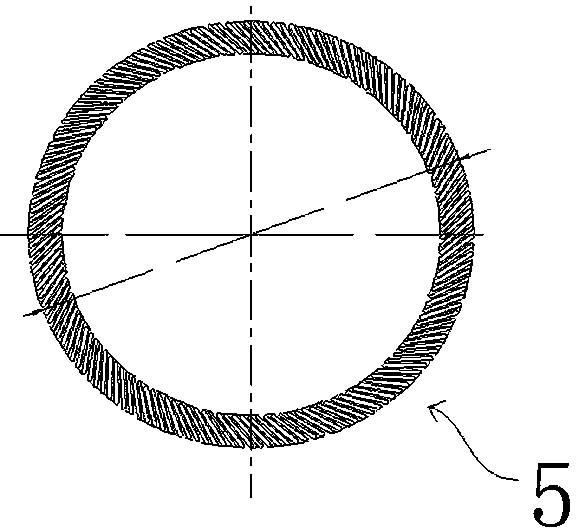
[0048] As another embodiment of the present invention, the spring contact fingers 5 may also be replaced by other forms of contact fingers, such as wristband contact fingers.

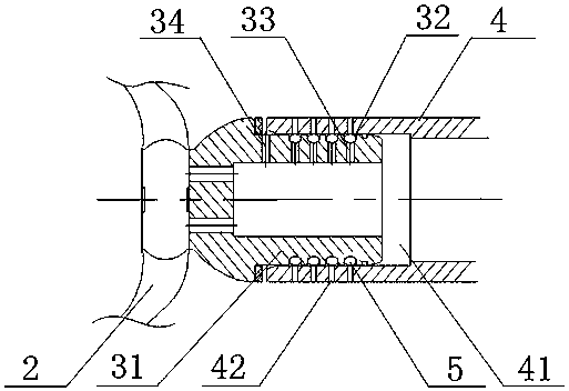
[0049] As another embodiment of the present invention, the insulators can also use other forms of insulators instead of pot insulators, as long as the electrical insulation between the electrical connection base and the housing can be realized, but other forms of insulators The effect is not as good as the pot insulator. The pot insulator can increase the creepage distance between the electrical connection seat and the shell, effectively preventing the risk of the insulator being broken down because the creepage distance is too short. The size of the case can be reduced.

[0050] A specific embodiment of the enclosed main busbar of the present invention has the same specific structure as that of the enclosed main busbar in the above-mentioned gas-insulated metal-enclosed switchgear, and will not be repe...


PUM


Abstract

The invention relates to the technical field of a high-voltage switchgear, and in particular to an electrical connection structure in a switchgear, a closed main bus and a gas-insulated metal-enclosed switchgear. The gas-insulated metal-enclosed switchgear comprises the closed main bus, wherein the closed main bus comprises the electrical connection structure, the electrical connection structure comprises an electrical connection seat and a conductive rod, one of the electrical connection seat and the conductive rod is provided with a male connector, the other one of the electrical connection seat and the conductive rod is provided with a female connector, touch fingers are arranged on a contact surface of the electrical connection seat and the conductive rod, and first heat dissipation holes are formed in the female connector and are corresponding to the touch fingers. The heat dissipation holes are formed in the conductive rod or the electrical connection seat and are corresponding to the positions of the touch fingers, so that heat generated at the touch fingers can be dissipated to a part outside the electrical connection structure through the shortest path and with the fastest speed, the temperature rise of the electrical connection structure is effectively reduced, the electrical connection structure can bear larger current flowing quantity, and the current-through capability of the closed main bus is improved.

Description

technical field [0001] The invention relates to the technical field of high-voltage switchgear, in particular to an electrical connection structure, a closed main bus bar and a gas-insulated metal-enclosed switchgear in the switchgear. Background technique [0002] At present, the closed main busbar of domestic 252kV gas-insulated metal-enclosed switchgear generally includes a shell and a conductive rod. The electrical connectors on the insulators are connected together. For example, an authorized announcement number is CN 201369531 Y, a Chinese patent titled a busbar for UHV test equipment discloses a high-voltage enclosed main busbar, including a shell, and a pot insulator is fixedly arranged inside the shell. An electrical connecting body is arranged in the center of the electrical connecting body, and a connecting groove of a conductive rod is arranged on the electrical connecting body, and the conductive rod is inserted into the connecting groove of the conductive rod....

Claims


Application Information

Patent Timeline
Patent Type & Authority Patents(China)
IPC IPC(8): H02G5/06H02G5/10H02B13/035H01R13/627H01R13/629H01R13/46
CPCH01R13/46H01R13/627H01R13/629H02B13/035H02G5/06H02G5/10
Inventor 王军飞庞庆平黄坤鹏高超楼胡劲涛刘静吴文利
Owner HENAN PINGGAO ELECTRIC
Why Eureka
Try Eureka