Flexible DC additional control method for suppressing subsynchronous oscillation
A sub-synchronous oscillation and additional control technology, applied in the direction of reducing/preventing power oscillation, power transmission AC network, etc., can solve the problem of limited sub-synchronous oscillation suppression effect, achieve fast response, strong versatility, and easy access
- Summary
- Abstract
- Description
- Claims
- Application Information
AI Technical Summary
Problems solved by technology
Method used
Image

Examples
Embodiment Construction
[0038] In order to make the technical means, creative features, goals and effects achieved by the present invention easy to understand, the technical solutions of the present invention will be further elaborated below in conjunction with specific embodiments.
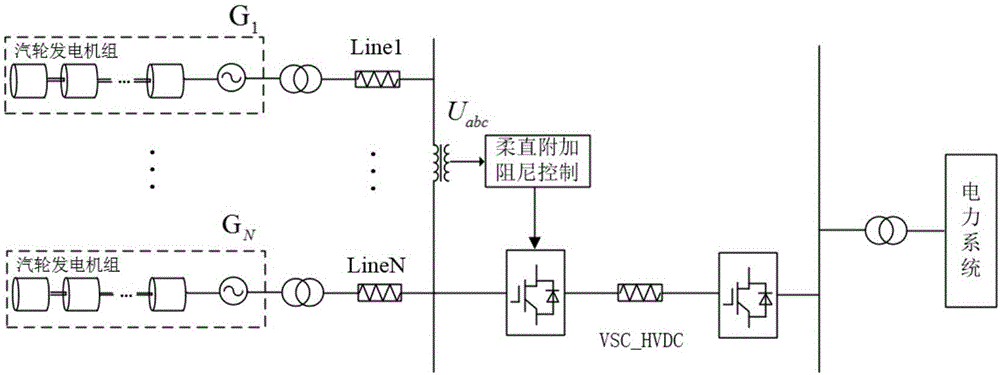
[0039] figure 1 Shown is a schematic diagram of the flexible DC topology and the DC damping additional control wiring to suppress subsynchronization. The side of the DC rectification station includes N sets of thermal power generators from G1 to GN that may generate subsynchronous oscillations. The distance between each unit and the commutation bus on the rectification side is represented by LineN. The voltage transformer on the side of the DC rectifier station will measure the AC voltage u of the commutation busbar abcSend it to the flexible DC sub-synchronous damping controller, and add the generated control output signal to the flexible DC controller.
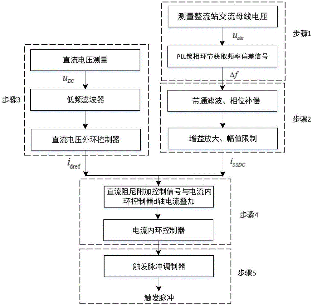
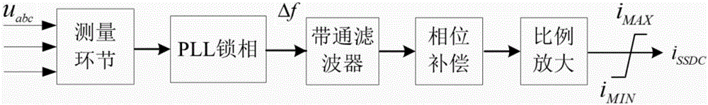
[0040] The flexible DC additional control method for suppressi...
PUM
 Abstract
Description
Claims
Application Information