
A AC-DC decoupling control method and its application in flexible DC transmission system

A decoupling control, AC-DC technology, applied in the direction of electrical components, etc., can solve the problems of long fault isolation time and power recovery time, non-real-time monitoring of the residual voltage value of the DC side, and threats to the safe operation of the converter, so as to improve safety. The effect of stability, economic loss reduction and equipment operation safety improvement

Active Publication Date: 2018-11-30
HUAZHONG UNIV OF SCI & TECH
View PDF3 Cites 2 Cited by
  • Summary
  • Abstract
  • Description
  • Claims
  • Application Information

AI Technical Summary

Problems solved by technology

The scheme of Kong Ming et al. has similarities with the scheme of CN104300569, the difference is that the residual voltage value of the DC side is not monitored in real time, but the residual voltage value of the DC side is artificially set to zero. The module capacitor voltage forms a closed-loop control, so there is a potential safety hazard of overcurrent or submodule capacitor overvoltage. In fact, it can be seen from Figure 12 in the above paper that during a DC fault, the DC current value rises from 1.6kA in the steady state to 8kA at the moment of the fault. The DC overcurrent multiple is as high as 5 times, which will pose a threat to the safe operation of the converter
In addition, the above existing technical solutions do not propose an effective fault ride-through scheme for the pole-to-ground DC fault of the pseudo-bipolar flexible direct current transmission system (or called symmetrical unipolar flexible direct current transmission system), so that the pseudo-bipolar flexible direct current transmission system The operation of the system still has the defects of long fault isolation time and power restoration time

Method used


Image

  • A AC-DC decoupling control method and its application in flexible DC transmission system
  • A AC-DC decoupling control method and its application in flexible DC transmission system
  • A AC-DC decoupling control method and its application in flexible DC transmission system

Examples


Embodiment Construction

[0054] In order to make the object, technical solution and advantages of the present invention clearer, the present invention will be further described in detail below in conjunction with the accompanying drawings and embodiments. It should be understood that the specific embodiments described here are only used to explain the present invention, not to limit the present invention. In addition, the technical features involved in the various embodiments of the present invention described below can be combined with each other as long as they do not constitute a conflict with each other.

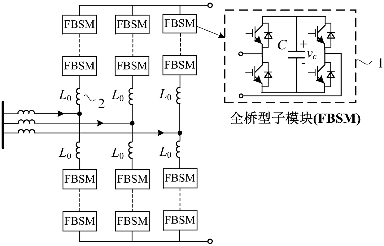
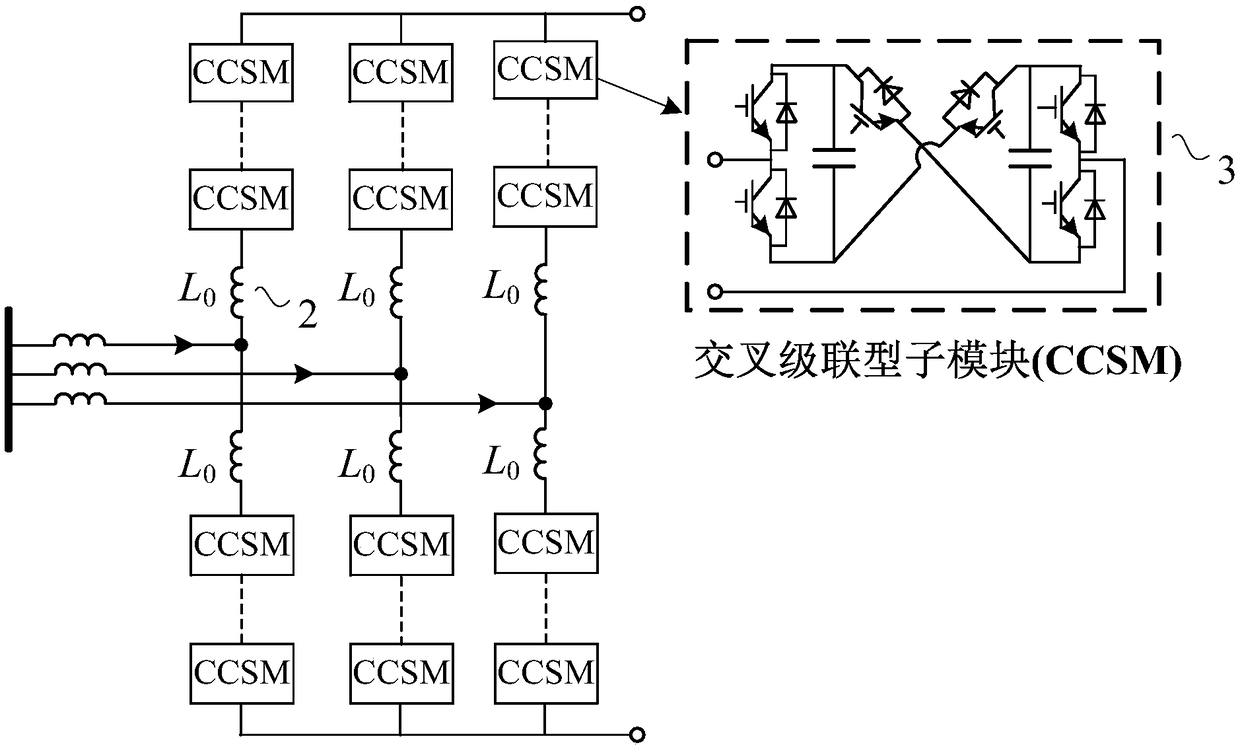
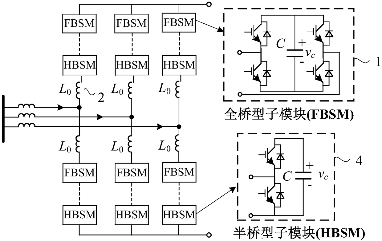
[0055] Figure 1 ~ Figure 4 It is a typical MMC topology applicable to the control method proposed by the present invention in the prior art. Such as Figure 1~4 shown, where figure 1 It is a full-bridge MMC, and each bridge arm is composed of multiple full-bridge sub-modules connected in series. figure 2 It is an MMC topology composed of cross-connected sub-modules, figure 2 Each bridge ...


PUM


Abstract

The invention discloses an AC / DC decoupling control method of a modular multi-level converter. The method comprises the steps as follows: DC control is added to current inner loop control and comprises positive DC control and negative DC control, so that an output of AC control, an output of positive DC control and an output of negative DC control are taken as main components of output voltage reference values of various phase bridge arms of an MMC; and control on the main components of the output voltage reference values of various phase bridge arms of the MMC can be achieved by controlling the reference values and the outputs of the AC control, the positive DC control and the negative DC control, thereby preventing the converter from being locked due to overcurrent of the bridge arms in a DC failure. The invention further discloses an application of the method in the flexible DC power transmission system. According to the method disclosed by the invention, the condition that AC and DC are maintained within a safety range can be ensured, so that DC fault ride-through of the overhead flexible DC power transmission system is achieved.

Description

technical field [0001] The invention belongs to the technical field of power system transmission and distribution, and more specifically relates to an AC / DC decoupling control method for a modular multilevel converter and its application in a flexible DC transmission system. Background technique [0002] Modular Multilevel Converter (MMC) technology has the advantages of modular structure and easy expansion. Since it was proposed, it has been widely used in the industry. So far, all the MMC HVDC transmission projects in the world have adopted the half-bridge type MMC technology based on the half-bridge sub-module (HBSM) or the same type of half-bridge sub-module (HBSM). Flat (Cascaded two level, CTL) technology. However, both the half-bridge MMC and CTL have the problem of being unable to cope with DC faults. After a DC fault occurs on the transmission line, the AC system will continue to provide fault current to the fault point through the freewheeling diode of the half-b...

Claims


Application Information

Patent Timeline
Patent Type & Authority Patents(China)
IPC IPC(8): H02J5/00
CPCH02J5/00
Inventor 林卫星向往文劲宇
Owner HUAZHONG UNIV OF SCI & TECH
Learn More