Water spraying system and waste gas treatment system

A technology of waste gas treatment and water spraying, which is applied in the direction of gas treatment, chemical instruments and methods, and the use of liquid separation agents, etc. It can solve the problems of reducing the service life of equipment, accumulating impurity particles in flue gas, and acidic solutions, so as to save waste , reduce pollution, save water use effect

Inactive Publication Date: 2017-03-22
绍兴市鼎赞环保科技有限公司
View PDF5 Cites 3 Cited by
  • Summary
  • Abstract
  • Description
  • Claims
  • Application Information

AI Technical Summary

Problems solved by technology

However, the solution in the traditional water spray system will accumulate impurity particles in the flue gas due to long-term recycling, and the solution will become acidic over time
However, the equipment mainly made of steel will be corroded under acidic conditions for a long time, which will reduce the service life of the equipment.

Method used


Image

  • Water spraying system and waste gas treatment system
  • Water spraying system and waste gas treatment system
  • Water spraying system and waste gas treatment system

Examples


Embodiment 1

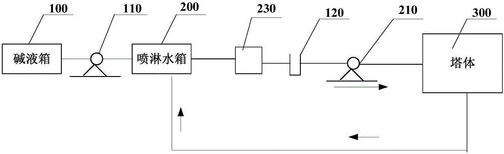
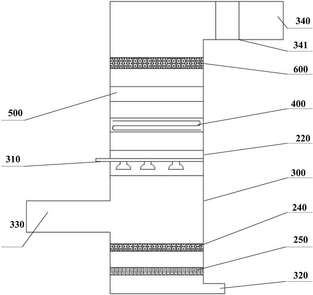
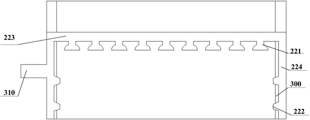
[0038] Such as figure 1 and figure 2 As shown, a water spray system provided in this embodiment includes: lye tank 100, metering pump 110, spray water tank 200, first water pump 210, pH probe 120, nozzle device 220, tower body 300 and control device The lye tank 100, the metering pump 110 and the spray water tank 200 are connected successively; the water outlet of the spray water tank 200, the first water pump 210, the tower body water inlet 310, the tower body water outlet 320 and the spray water tank 200 water inlet are connected successively , form the first circulation system, the pH probe 120 is arranged in the first circulation system; the nozzle device 220 is connected with the tower body water inlet 310, and is arranged in the tower body 300; the smoke inlet 330 of the tower body 300 is arranged on the nozzle device 220 Below, the smoke outlet 340 of the tower body 300 is set above the nozzle device 220; the pH probe 120, the control device and the metering pump 110 ...

Embodiment 2

[0050] Such as figure 2 and Figure 4 As shown, this embodiment provides an exhaust gas treatment system, including: a condensing device, a high-voltage electrostatic device 500, an induced draft fan 341 and a water spray system; the condensing device includes a condensed water tank 400, a second water pump 420, a condensing pipe 410, and a first Two cooling towers 430; the water outlet of the condensed water tank 400, the second water pump 420, the condensation pipe 410, the second cooling tower 430, and the water inlet of the condensed water tank 400 are connected in sequence to form a second circulation system; the condensed water pipe 410 is arranged above the sprinkler device 220 , the high-voltage electrostatic device 500 is arranged between the condensing device and the smoke outlet 340 of the tower body 300 , and the induced draft fan 341 is arranged at the smoke outlet 340 .

[0051] Among them, the working principle of the high-voltage electrostatic device 500 is t...


PUM


Abstract

The invention relates to the technical field of environmental protection, and particularly relates to a water spraying system and a waste gas treatment system. The water spray system comprises a lye tank, a metering pump, a spray water tank, a first water pump, a PH probe, a sprayer device, a tower body and a control device, wherein the lye tank, the metering pump and the spray water tank are sequentially connected; the water outlet of the spray water tank, the first pump, the water inlet of the tower body, the water outlet of the tower body and the water inlet of the spray water tank are communicated sequentially to form a first circulating system; the PH probe is arranged in the first circulating system; the sprayer device is connected with the water inlet of the tower body, and is arranged in the tower body; a smoke inlet of the tower body is formed in the lower side of the sprayer device, and a smoke outlet of the tower body is formed in the upper side of the sprayer device; and the PH probe, the control device and the metering pump are electrically connected sequentially. The water spraying system can be used for automatically adjusting the PH value of the solution in the water spraying system, so that equipment corrosion is reduced, and the service life of the equipment is prolonged.

Description

technical field [0001] The invention relates to the technical field of environmental protection, in particular to a water spray system and a waste gas treatment system. Background technique [0002] Since the reform and opening up, my country's industrial technology has developed rapidly. At the same time, due to the combustion of a large amount of fuel and the emission of industrial waste gas, the air quality is deteriorating day by day. At present, the awareness of environmental protection in our country is constantly strengthening, and all enterprises put the protection of the environment at the forefront of enterprise development. Therefore, the waste gas should be treated before it is discharged. [0003] At present, most exhaust gas treatment systems are equipped with a water spray system. The water spray system can reduce the temperature of the smoke when it is discharged, and can also dissolve some particles or water-soluble gases in the smoke, reducing the emission ...

Claims


Application Information

Patent Timeline
Patent Type & Authority Applications(China)
IPC IPC(8): B01D47/06B01D53/18B01D50/00
CPCB01D47/06B01D50/00B01D53/002B01D53/1412B01D53/18B01D2252/103B01D2258/02B01D2259/124
Inventor 张淦
Owner 绍兴市鼎赞环保科技有限公司
Why Eureka
Try Eureka