
Electrically controlled dryer assembly with ECU (Electronic Control Unit) controller and control method

A control method and dryer technology, applied in chemical instruments and methods, separation methods, and separation of dispersed particles, etc., can solve problems such as complex line layout, control logic, input and output signal constraints, and shortened service life

Active Publication Date: 2017-03-22
ZHEJIANG VIE SCI & TECH
View PDF10 Cites 2 Cited by
  • Summary
  • Abstract
  • Description
  • Claims
  • Application Information

AI Technical Summary

Problems solved by technology

However, the controller and pressure sensor of this type of dryer need to be connected externally, which makes the wiring layout complicated, and the control logic, input and output signals, etc. are restricted.
The most important thing is that the dryers currently used usually realize the functions of unloading and backflushing after the pressure reaches the unloading pressure. If they are under a certain pressure (less than the unloading pressure) for a long time, the dryer cannot Implement unloading and backflushing functions, the molecular sieve of the drying tank is easy to absorb water and saturate, greatly reducing its service life

Method used


Image

  • Electrically controlled dryer assembly with ECU (Electronic Control Unit) controller and control method
  • Electrically controlled dryer assembly with ECU (Electronic Control Unit) controller and control method
  • Electrically controlled dryer assembly with ECU (Electronic Control Unit) controller and control method

Examples


Embodiment Construction

[0023] In order to make the objectives, technical solutions and advantages of the present invention clearer, the following further describes the present invention in detail with reference to the accompanying drawings and embodiments. It should be understood that the specific embodiments described herein are only used to explain the present invention, but not to limit the present invention.

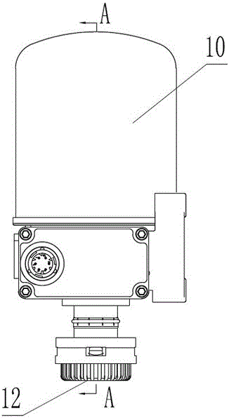
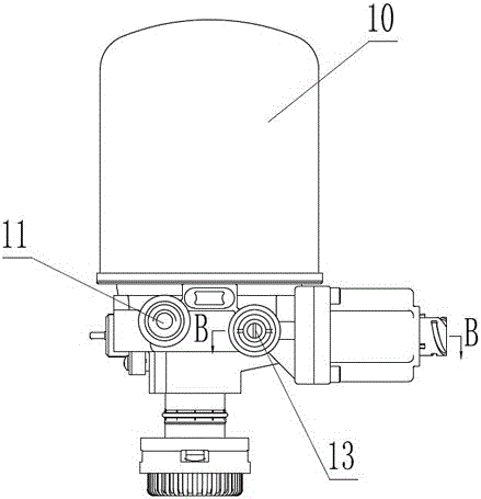
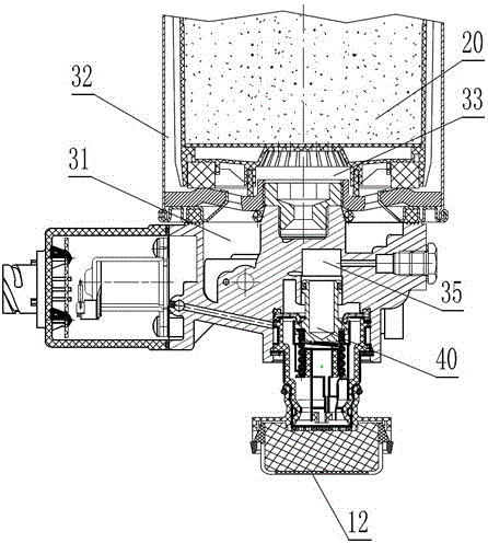
[0024] Such as Figure 1-4 As shown, an electronically controlled dryer assembly with an ECU controller in this embodiment includes a dryer body 10 and a drying tank 20 arranged in the dryer body 10, wherein the drying tank 20 is provided with a molecular sieve. The dryer body 20 of this embodiment is provided with an air inlet 11, an air outlet 13 and an air outlet 12.

[0025] In this embodiment, the dryer body 10 is also provided with a cavity A31, a cavity B32, a cavity C33, a cavity D34, a cavity E35, an unloading solenoid valve assembly 60, a blowback solenoid valve assembly 70, The ECU...


PUM


Abstract

The invention relates to a dryer belonging to the field of automobiles, and specifically discloses an electrically controlled dryer assembly with an ECU (Electronic Control Unit) controller and a control method. The electrically controlled dryer assembly with the ECU controller has a protection function, namely when the pressure value of the dryer assembly is less than unloading pressure for a long time and reaches a set forced unloading pressure value for a period of time exceeding set time, the ECU controller controls an unloading electromagnetic valve assembly to be started to realize forced unloading and back flushing to protect the regeneration effect of a drying tank molecular sieve, and the service life of a dryer is greatly prolonged.

Description

Technical field [0001] The invention relates to a dryer used in the automotive field, in particular to an electronically controlled dryer assembly with an ECU controller and a control method. Background technique [0002] In the traditional dryer used in the automotive field, the air compressor has no start-stop function, which has poor energy-saving effect, and the use of the drying tank cannot be monitored. With the advancement of science and technology, the most commonly used dryers now include solenoid valves to realize electrical control. However, the controller and pressure sensor of this type of dryer need to be connected externally, which makes the circuit layout complicated and restricts the control logic and input and output signals. The most important thing is that the dryers currently in use usually only realize the functions of unloading and backflushing after the pressure reaches the unloading pressure. If the dryer is under a certain pressure (less than the unload...

Claims


Application Information

Patent Timeline
IPC IPC(8): B01D53/26
CPCB01D53/261B01D2253/116
Inventor 陈钢强王保松钱烜辉
Owner ZHEJIANG VIE SCI & TECH
Learn More