Combined sliding table driven by hydraulic cylinders and gears

A gear-driven, hydraulic cylinder technology, applied in the field of machinery, achieves the effects of low cost, low manufacturing cost and improved service life

Active Publication Date: 2017-03-22
LUOYANG LIWEI TECH
View PDF8 Cites 3 Cited by
  • Summary
  • Abstract
  • Description
  • Claims
  • Application Information

AI Technical Summary

Problems solved by technology

[0008] However, these slide tables all have the technical problem that the oil cylinder of each slide table can only control the movement of the slide table body within the control stroke of the oil cylinder itself.

Method used


Image

  • Combined sliding table driven by hydraulic cylinders and gears
  • Combined sliding table driven by hydraulic cylinders and gears

Examples


Embodiment 1

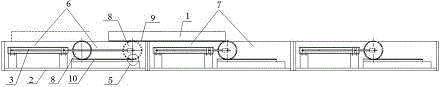
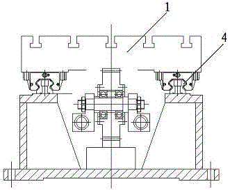
[0047] like figure 1 , figure 2 As shown, the combination sliding table driven by hydraulic cylinder and gear in this patent includes a controller, a sliding table body 1, a first sliding table mechanism 6, a second sliding table mechanism 7 until a fourth sliding table mechanism, and the sliding table mechanism Both include a driving gear, a sliding table seat, a linear guide rail, a driving oil cylinder, a rack of the sliding table seat, and a position sensing device for the sliding table body; the driving oil cylinder 3 is a one-way oil cylinder.

[0048] The position sensing device of the sliding table body is set on the fixed part that can sense and accept the position signal of the sliding table body 1, to receive the position signal of the sliding table body 1, and transmit the signal to the controller; the controller is used to control the hydraulic cylinder and gear The action of the driven combination slide table. The lower part of the sliding table body 1 is prov...


PUM


Abstract

The invention discloses a combined sliding table driven by hydraulic cylinders and gears. The combined sliding table comprises a controller, a sliding table body, a first sliding table mechanism, a second sliding table mechanism,..., and an Nth sliding table mechanism, wherein N is the total number of the sliding table mechanisms and is larger than or equal to three. Each sliding table mechanism comprises a drive gear, a sliding table base, a linear guide rail, a drive oil cylinder, a sliding table body rack, a sliding table base rack and a sliding table body position induction device. The sliding table bases of the sliding table mechanisms are combined together in an end butt joint manner and jointly use one sliding table body. The linear guide rails are connected. Rotation shafts are arranged in the middles of the drive gears and fixed to power output ends. The sliding table base racks are parallel to telescopic oil cylinders. Each sliding table body rack and the sliding table base rack of the adjacent sliding table mechanism can be partially crossed left and right. Due to the gear and double-rack transmission form, double amplification of the stroke and the speed of the drive oil cylinders can be achieved, conversion of drive force of two sliding bases to the sliding table body is achieved through the butt joint function, and accordingly, the cross-region operation of the sliding table body is achieved.

Description

technical field [0001] The invention relates to a technology in the mechanical field, in particular to a combined sliding table driven by a hydraulic cylinder and a gear. Background technique [0002] Conventional mechanical slides are the main bed of combined machine tools, counter milling machines, and other special machine tools. The working principle of the mechanical slide table is that the slide plate moves longitudinally on the bed, because of the screw drive and the role of the gearbox. Various running speeds such as fast and slow can be obtained. After the workpiece is installed on the mechanical slide table, it can perform reciprocating motion, and after installing the power head and other related accessories on the slide table, various cutting, drilling, and boring movements can be performed on the workpiece through the movement of the slide table. Combining multiple sliding tables of different specifications can process complex parts or carry out mass productio...

Claims


Application Information

Patent Timeline
Patent Type & Authority Applications(China)
IPC IPC(8): B23Q1/26
CPCB23Q1/26
Inventor 石峰徐可立
Owner LUOYANG LIWEI TECH
Why Eureka
Try Eureka