A machine tool temperature control system

A technology of temperature control system and machine tool, applied in the direction of manufacturing tools, metal processing machinery parts, metal processing equipment, etc., can solve problems such as hierarchical control, selection of cooling mode, tool damage, etc.

Active Publication Date: 2018-10-09
张武昌
View PDF7 Cites 0 Cited by
  • Summary
  • Abstract
  • Description
  • Claims
  • Application Information

AI Technical Summary

Problems solved by technology

[0002] A machine tool is a machine that processes metal blanks into mechanical parts. Due to frequent cutting, extrusion and friction between the workpiece and the processing tool, the temperature of the processing tool and the workpiece is very high. When the temperature at the processing place is too high, it will It will affect the processing tool and workpiece, resulting in the decrease of processing accuracy and damage of the tool. At this time, it is necessary to cool down the processing place; at present, the liquid spray pipe is usually used to spray the processing part to cool the processing tool and the workpiece. Some machine tools use coolant with lubricating effect, so that during the cooling process, the lubrication of the processing tool and the workpiece can be realized; but this cooling method is to continuously cool the processing area, often to achieve better However, the temperature change is complex and the temperature change trend is changeable, resulting in a variety of temperature distributions in the process of cooling the processing place. At this time, it is difficult to manually The temperature distribution regulates the working status of each component in stages, and it is even more difficult to select a suitable cooling mode according to different temperature distributions, which affects the cooling effect of the processing area to a large extent, and also hinders the processing of the processing area to a certain extent. Application and Development of Staged Cooling Technology

Method used


Image

  • A machine tool temperature control system

Examples


Embodiment Construction

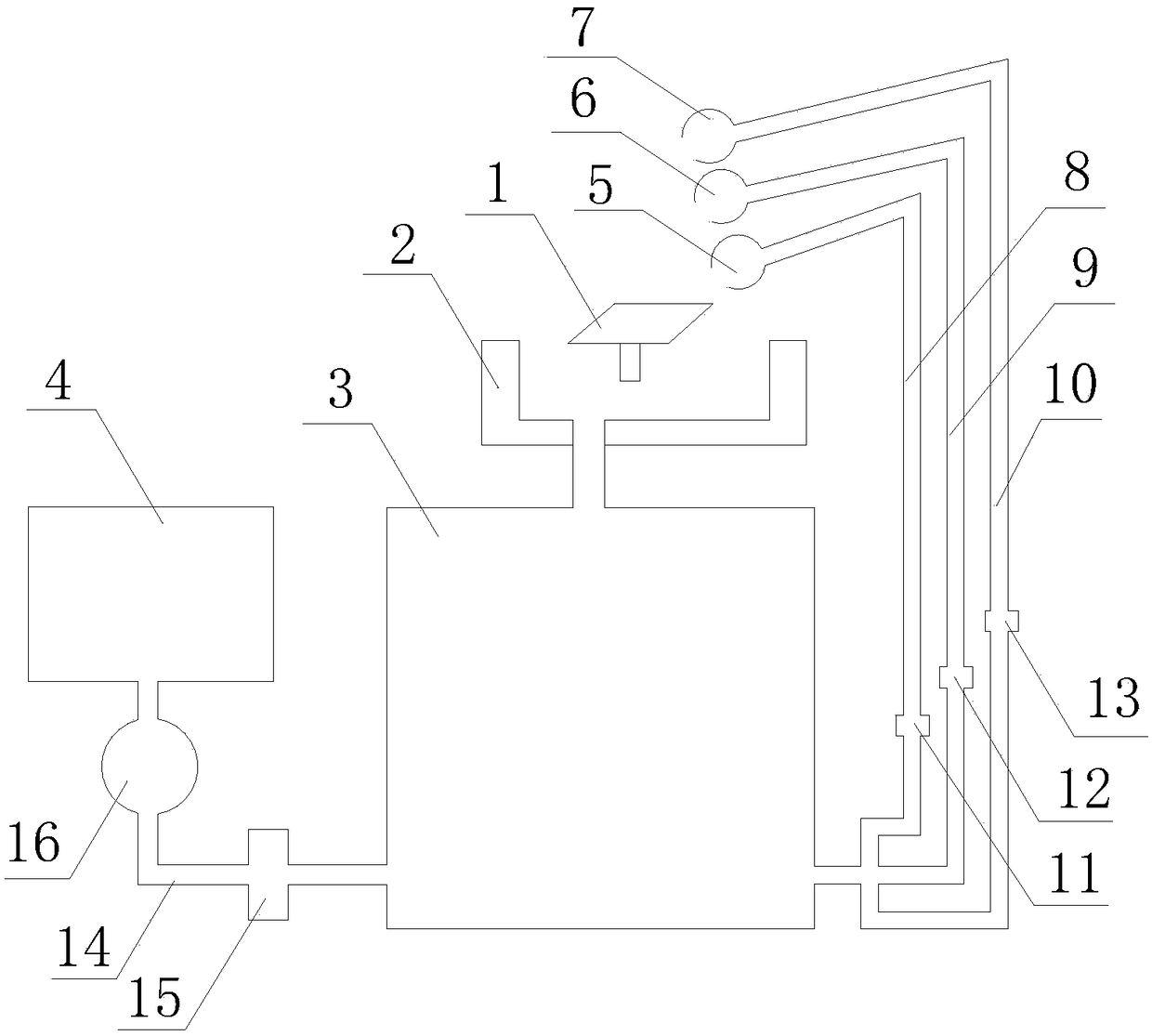
[0024] Such as figure 1 as shown, figure 1 It is a machine tool temperature control system proposed by the present invention.

[0025] refer to figure 1 , the machine tool temperature control system that the present invention proposes, comprises: workbench 1, effluent tank 2, cooling tank 3, temperature sensor, coolant tank 4 and controller;

[0026] A processing station is provided on the workbench 1, and a first nozzle 5, a second nozzle 6 and a third nozzle 7 are arranged at the processing station;

[0027] The liquid accumulation tank 2 is arranged under the workbench 1, and is used to collect the liquid produced during the cooling process of the processing station. The liquid accumulation tank 2 has an opening at the top and a first liquid outlet at the bottom; a filter is provided at the first liquid outlet. The net is used to filter the waste in the liquid to prevent the waste in the liquid from flowing to the processing station again, which will affect the machining...


PUM


Abstract

The invention discloses a machine tool temperature control system. The machine tool temperature control system comprises a worktable, a liquid collecting box, a cooling box, a temperature sensor, a cooling liquid box and a controller; a machining station is arranged on the worktable, and is provided with a first nozzle, a second nozzle and a third nozzle; the liquid collecting box is arranged below the worktable; the liquid collecting box is opened at the top, and is provided with a first liquid outlet at the bottom; a liquid inlet, a second liquid outlet and a third liquid outlet are formed in the cooling box; the liquid inlet is communicated with the first liquid outlet by a pipeline; the temperature sensor is arranged in the liquid inlet of the cooling box for detecting the temperature of liquid flowing in the cooling box; the cooling liquid box is in pipeline communication with the third liquid outlet through a fourth pipe; an electromagnetic valve and an electronic pump are arranged on the fourth pipe; the controller is communicated with the temperature sensor, the electromagnetic valve and the electronic pump; multiple cooling modes are preset in the controller; and the controller selects the cooling modes according to detecting values of the temperature sensor and/or the change tendency of the detecting values.

Description

technical field [0001] The invention relates to the technical field of machine tool cooling, in particular to a machine tool temperature control system. Background technique [0002] A machine tool is a machine that processes metal blanks into mechanical parts. Due to frequent cutting, extrusion and friction between the workpiece and the processing tool, the temperature of the processing tool and the workpiece is very high. When the temperature at the processing place is too high, it will It will affect the processing tool and workpiece, resulting in the decrease of processing accuracy and damage of the tool. At this time, it is necessary to cool down the processing place; at present, the liquid spray pipe is usually used to spray the processing part to cool the processing tool and the workpiece. Some machine tools use coolant with lubricating effect, so that during the cooling process, the lubrication of the processing tool and the workpiece can be realized; but this coolin...

Claims


Application Information

Patent Timeline
Patent Type & Authority Patents(China)
IPC IPC(8): B23Q11/14B23Q11/00
CPCB23Q11/0089B23Q11/146
Inventor 张武昌
Owner 张武昌
Why Eureka
Try Eureka