Optical lens and injection molding mold thereof

An optical lens and injection molding technology, applied in the field of optical lenses, can solve the problems affecting the optical performance of the lens, fast flow rate, etc., achieve the effect of strengthening stress intensity, strong force and tolerance tolerance, and improving yield rate

Inactive Publication Date: 2017-03-22
EVERREADY PRECISION IND
View PDF3 Cites 2 Cited by
  • Summary
  • Abstract
  • Description
  • Claims
  • Application Information

AI Technical Summary

Problems solved by technology

[0005] However, the channel height of the two ring sides of the cavity 15 of the conventional injection molding mold 1 is higher than the channel height of the central region of the cavity 15 of the conventional injection molding mold 1, and therefore the melt will be less resistant The ground flows through the sides of the two rings, so the flow velocity on the sides of the two rings will be faster than that in the central area, which will lead to Figure 4 Shows the flow of the melt in the chamber during lens manufacturing
However, its disadvantage is that before the melt 8 has completely filled the central area (that is, the optical effective area of ​​the lens), the melt 8 has already filled the two ring sides (that is, the non-optical effective area of ​​the lens), and when the final lens is formed , there will be voids or fusion lines 19 formed in the central area of ​​the lens (that is, the optically effective area of ​​the lens), which will seriously affect the optical performance of the lens

Method used


Image

  • Optical lens and injection molding mold thereof
  • Optical lens and injection molding mold thereof
  • Optical lens and injection molding mold thereof

Examples


Embodiment Construction

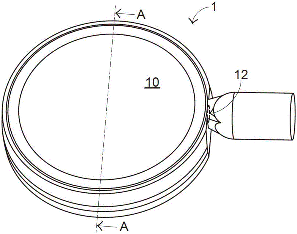
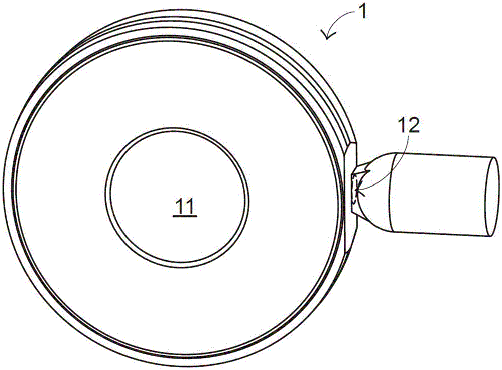
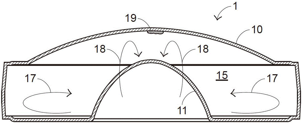
[0035] Figure 5 It is a three-dimensional schematic diagram of the injection molding mold of the optical lens of the present invention; Image 6 It is a three-dimensional schematic diagram of another angle of the injection molding mold of the optical lens of the present invention; Figure 7 for Figure 5 The sectional view in the direction of the B-B line segment. Such as Figure 5 to Figure 7 As shown, the optical lens injection molding mold 2 of the present invention includes a disc-shaped mold base 21 and a nozzle 22, the nozzle 22 is connected with the disc-shaped mold base 21, and its internal space is also communicated. The upper surface of the disc-shaped mold base 21 arches upwards in an arc shape, and a curved surface vertex P is formed at the central point to manufacture an optical lens with a similar curved surface.

[0036] A mold cavity chamber 210 is defined inside the disc-shaped mold base 21 (please refer to Figure 7 ) and the gate 211 communicating with...


PUM


Abstract

The invention provides an optical lens and an injection molding mold thereof. The injection molding mold of the optical lens comprises a disc-shaped mold seat and a nozzle. A mold cavity chamber and a sprue communicating with the mold cavity chamber are defined by the disc-shaped mold seat. The mold cavity chamber comprises an optical effective area center runner and a non-optical effective area circumferential runner. The optical effective area center runner is defined between an upper curved surface and a lower curved surface in the disc-shaped mold seat. The non-optical effective area circumferential runner surrounds and communicates to the optical effective area center runner and communicates with the sprue. A plurality of turbulent flow structures are formed at the positions, on the non-optical effective area circumferential runner, of the disc-shaped mold seat. The nozzle is connected to the disc-shaped mold seat. Melt is injected into the mold cavity chamber through the sprue. The flow speed of the melt on the non-optical effective area circumferential runner is disturbed by the multiple turbulent flow structures, the optical effective area center runner is preferentially filled with the melt, and therefore an optical effective area of the optical lens cannot be generated with defects so as to increase the yield of the optical lens.

Description

technical field [0001] The present invention relates to an injection molding mold and an optical lens for corresponding injection, in particular to an injection molding mold with high production yield and an excellent optical lens for corresponding injection. Background technique [0002] With the advancement of science and technology, it has gradually developed towards the process of miniaturization of objects. In addition to the smaller and smaller diameter requirements of optical lenses, there is also a requirement for thinner and thinner thickness, that is, optical lenses are moving toward miniaturization. develop. At the same time, due to the diversification of functions of electronic devices, the industry has begun to have situations and demands for mounting optical lenses on mobile electronic devices. For example, optical lenses and laser light sources are combined to form an application function of illuminating structured light. [0003] figure 1 It is a three-dim...

Claims


Application Information

Patent Timeline
Patent Type & Authority Applications(China)
IPC IPC(8): B29C45/26B29C45/30G02B3/00
CPCG02B3/0031G02B3/0043B29C45/2602B29C45/30B29D11/00538
Inventor 陈志隆颜智敏陈进成
Owner EVERREADY PRECISION IND
Why Eureka
Try Eureka