
Magnetic levitation rotor wing system and helicopter with same

A technology of rotorcraft and magnetic levitation, which is applied in the direction of rotorcraft, propellers, motor vehicles, etc., can solve the problems of inconsistent rotation of the blades, affecting the lift of the tip of the blade, and complex systems, so as to improve the lift effect of the rotor, compact structure, and system streamlined effect

Active Publication Date: 2017-03-22
CHINA HELICOPTER RES & DEV INST
View PDF7 Cites 26 Cited by
  • Summary
  • Abstract
  • Description
  • Claims
  • Application Information

AI Technical Summary

Problems solved by technology

[0004] The power of the conventional rotor device is mechanically converted and transmitted through the engine and the transmission, and there is a power loss and the system is complicated; there is air convection above and below the blade section at the blade tip of the rotor blade, which reduces the airflow above and below the blade section. The pressure difference of the rotor blade affects the ability of the blade tip to generate lift; and the blade is exposed, which will collide with external objects and affect flight safety. At the same time, the noise generated by the rotor blade is not shielded and is directly transmitted to the outside world. The overall noise is large
[0005] Since the blade rotates at a position with a larger radius, the linear speed is faster, and the lift generated by this part is also large. Generally, the resultant lift force of the blade is at the position of about 70% of the blade radius at the tip of the blade, that is, the position away from the rotor axis. , while the bearing position of the conventional rotor device is at the center, that is, the rotor shaft, so the moment arm between the lift force of the blade and the bearing position of the rotor shaft is relatively long, resulting in a large bending moment for the blade, propeller hub and rotor shaft, resulting in vibration Large, low fatigue life
[0006] Publication number CN101693470B Chinese invention patent provides a kind of magnetic levitation electric power rotor flying saucer. Publication number is that CN102085912A Chinese invention patent application provides a kind of disc-shaped magnetic levitation ring-wing aircraft. The rotor device in the above two patents or patent applications Two sets of maglev guide rails, the rotor inner ring and the rotor outer ring, are used. The system is relatively complicated, and the overall weight of the rotor device is too large. At the same time, there are also aerodynamic loads on the rotor blades in different directions due to the superposition of airflow speeds in a complex airflow environment. Inconsistency, the resulting inconsistency in the rotational movement of each blade, there is a possibility that the blade may be misaligned on the inner and outer ring guide rails, and serious problems will cause the blade to be stuck

Method used


Image

  • Magnetic levitation rotor wing system and helicopter with same
  • Magnetic levitation rotor wing system and helicopter with same
  • Magnetic levitation rotor wing system and helicopter with same

Examples


Embodiment Construction

[0036] In order to make the objectives, technical solutions and advantages of the present invention clearer, the technical solutions in the embodiments of the present invention will be described in more detail below in conjunction with the drawings in the embodiments of the present invention. In the drawings, the same or similar reference numerals denote the same or similar elements or elements having the same or similar functions throughout. The described embodiments are some, but not all, embodiments of the invention. The embodiments described below by referring to the figures are exemplary and are intended to explain the present invention and should not be construed as limiting the present invention. Based on the embodiments of the present invention, all other embodiments obtained by persons of ordinary skill in the art without creative efforts fall within the protection scope of the present invention. Embodiments of the present invention will be described in detail below ...


PUM


Abstract

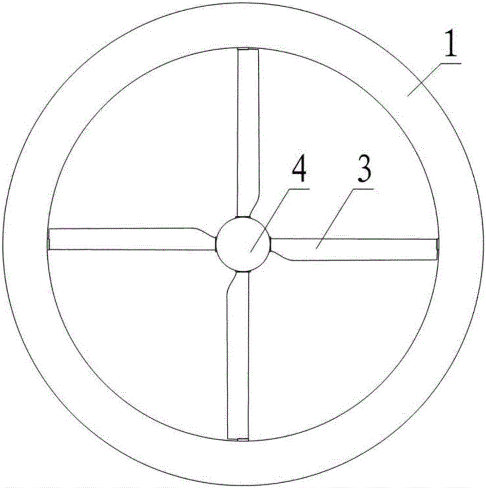
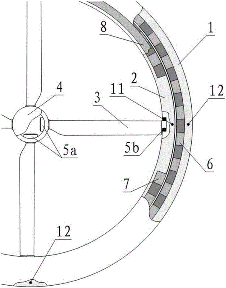
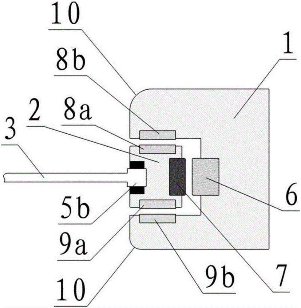
The invention relates to a magnetic levitation rotor wing system and a helicopter with the same and the field of aviation, in particular to the technical field of rotor wings. The magnetic levitation rotor wing system comprises a rotor wing ring (2) and a rail ring (1), wherein the rotor wing ring (2) is connected with a rotor wing propeller point, and the rail ring (1) provides magnetic suspension force for the rotor wing ring (2). Magnetic suspension force provided by the rail ring (1) includes a driving device capable of driving blades to rotate and a suspension device capable of enabling the propeller point to suspend. A first deflection driving mechanism is arranged on the root portions of the blades of the rotor wing so that first deflection angles of the root portions of the blades can be provided, and a second deflection driving mechanism is arranged on the rotor wing ring (2) so that second deflection angles of the points of the blades can be provided. According to the magnetic levitation rotor wing system and the helicopter with the same, only an outside rail ring is needed to drive the rotor wing ring, and the blades are connected by a central connecting component; and the requirement of independent variable pitch of the rotor wing is guaranteed, partial load of the blades is counteracted with one another through the central connecting component, integrality of the rotor wing ring is increased, and working reliability of improved.

Description

technical field [0001] The invention belongs to the field of overall design of helicopters, and in particular relates to a magnetic suspension rotor system and a helicopter with the same. Background technique [0002] The rotor of the rotorcraft generates aerodynamic force through rotation, which provides lift for flight, so that the helicopter can take off and land vertically, with flexible take-off and landing sites and a wide range of operations. While providing lift, the rotor can also produce the steering force required for flight in all directions. [0003] A conventional rotor device is composed of rotor blades, a rotor hub, and a rotor shaft. The rotor blades are installed on the rotor hub. The rotor hub is connected to the transmission system through the central rotor shaft. The driving force of the power system is decelerated through the transmission device through multi-stage gear transmission. Finally, it is transmitted to the rotor shaft, which then drives the ...

Claims


Application Information

Patent Timeline
Patent Type & Authority Applications(China)
IPC IPC(8): B64D27/02B64D27/26B64C27/12B64C11/32B64C27/00
CPCB64C11/32B64C27/006B64C27/12B64D27/02B64D27/40
Inventor 刘衍涛
Owner CHINA HELICOPTER RES & DEV INST
Learn More