Pressurization and dehumidification device for cabin of marine wind turbine generator system

A technology for wind turbines and nacelles, which is used in wind turbines, wind turbine monitoring, wind power generation, etc., can solve problems such as damage to metal parts, corrosion of metal parts, and reduction of service life, so as to reduce air humidity, increase internal pressure, The effect of preventing erosion

Pending Publication Date: 2017-03-22
GUODIAN UNITED POWER TECH LIANYUNGANG CO LTD
View PDF7 Cites 1 Cited by
  • Summary
  • Abstract
  • Description
  • Claims
  • Application Information

AI Technical Summary

Problems solved by technology

It is easy to cause damage to the metal parts in the wind turbine. The development of offshore wind turbines must take measures to

Method used


Image

  • Pressurization and dehumidification device for cabin of marine wind turbine generator system
  • Pressurization and dehumidification device for cabin of marine wind turbine generator system
  • Pressurization and dehumidification device for cabin of marine wind turbine generator system

Examples


Embodiment 1

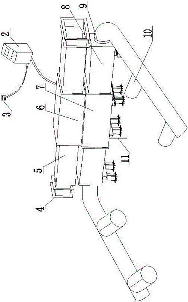
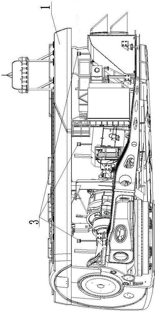
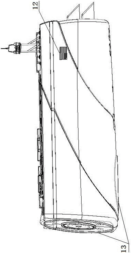
[0026] Embodiment 1, with reference to figure 1 , figure 2 and image 3 , a kind of pressurization and dehumidification device for the nacelle of an offshore wind power generating set is characterized in that it includes a booster pump 6 and a heat exchanger 7 arranged in the nacelle cover 1, a PLC 2 and a device for detecting and collecting pressure and humidity signals in the nacelle cover The sensor 3 of the booster pump is connected with the heat exchanger through the air pipeline, and a suction pipe 5 is arranged on the side of the booster pump, and the suction port 4 of the suction pipe is connected with the air intake port 4 provided on the outer wall of the nacelle cover. The tuyeres are connected, and an exhaust pipe 8 is arranged on the side of the heat exchanger. The exhaust port 9 of the exhaust pipe is arranged inside the nacelle cover, and a drain pipe 11 leading to the outside of the nacelle cover is arranged at the bottom of the heat exchanger. , the booster...

Embodiment 2

[0027] Embodiment 2, in the pressurization and dehumidification device for the nacelle of an offshore wind power generating set described in Embodiment 1: the suction pipes are arranged symmetrically on both sides of the booster pump, one on each side.

Embodiment 3

[0028] Embodiment 3, in the pressurization and dehumidification device for the nacelle of an offshore wind power generating set described in Embodiment 1 or 2: the exhaust pipes are arranged symmetrically on both sides of the heat exchanger, one on each side.


PUM


Abstract

The invention relates to a pressurization and dehumidification device for a cabin of a marine wind turbine generator system. The pressurization and dehumidification device comprises a booster pump, a heat exchanger, a PLC and sensors for detecting and collecting pressure signals and humidity signals in a cabinet cover, wherein the booster pump and the heat exchanger are arranged in the cabinet cover. The booster pump is connected with the heat exchanger through a gas pipeline. Suction pipes are arranged on the side face of the booster pump. Suction end openings of the suction pipes are connected with an air inlet formed in the outer wall of the cabinet cover. Exhaust pipes are arranged on the side face of the heat exchanger. Exhaust end openings of the exhaust pipes are arranged in the cabinet cover. A drainage pipeline communicating with the exterior of the cabinet cover is arranged at the bottom of the heat exchanger. The booster pump, the heat exchanger and the sensors are connected with the PLC through cables. By the adoption of the pressurization and dehumidification device, the functions of increasing the internal pressure of the cabinet cover and reducing the air humidification of the cabinet cover are achieved, at the moment, the internal pressure of the cabinet cover is greater than the external pressure of the cabin cover, external damp air can be isolated, and erosion of salt fog to internal parts of the cabinet cover is prevented effectively.

Description

technical field [0001] The invention relates to a pressurization and dehumidification device, in particular to a pressurization and dehumidification device for offshore wind power generators. Background technique [0002] At present, among various new energy sources, the technology of wind power generation is relatively mature, and the degree of industrialization is relatively high, but most of the wind farms are built in sparsely populated areas. The coastal cities with a large population are the major consumers of energy. Our wind farms are far away from the power load center, which creates certain obstacles to the transmission of wind power and the connection to the power grid. Offshore wind power development is not only close to coastal cities, the wind resources are better than inland, and it does not occupy land resources. Offshore wind power is quietly rising and will become an important form of energy. Wind farms are gradually developing from inland and coastal are...

Claims


Application Information

Patent Timeline
IPC IPC(8): F03D80/00F03D80/80F03D17/00
CPCF05B2260/64F05B2260/95Y02E10/72
Inventor 王璐陈波张蕾王洋
Owner GUODIAN UNITED POWER TECH LIANYUNGANG CO LTD
Why Eureka
Try Eureka