Integral mobile natural gas liquefaction device

A liquefaction device and natural gas technology, applied in liquefaction, refrigeration, liquefaction, solidification, etc., can solve problems such as long construction period, difficulty in natural gas development, unreachable pipeline laying, etc., to improve the degree of automation, solve the problem of no water source, Easy to move and assemble

Active Publication Date: 2017-03-22
宁夏凯添燃气发展股份有限公司
View PDF9 Cites 4 Cited by
  • Summary
  • Abstract
  • Description
  • Claims
  • Application Information

AI Technical Summary

Problems solved by technology

[0004] Traditional LNG liquefaction plants have complex preparation procedures, high investment costs, long construction period, large floor area, complex process, high overall energy consumption, limited scope of application, and are not suitable for the use of gas in isolated wells and single wells in remote mountainous areas.
Due to the difficulty in developing unconventional natural gas, the geographical location of gas wells is complicated, and the laying of pipelines is out of reach. At present, most of the equipment in the existing technology is divided into different modules according to their functions, mainly modular mobile liquefaction equipment. , in which the refrigeration process mainly adopts a relatively mature nitrogen expansion process; the absorption tower and regeneration tower adopt a single high tower, the equipment height is high, and there are limitations in transportation
Therefore, in order to solve the practical problems of traditional liquefaction plants, such as large floor area, long construction period, high cost, low integration, and non-movability, the applicant developed a low-tower and multi-tower series connection to realize decarburization and amine The purpose of liquid regeneration is to provide a balanced integrated mobile natural gas liquefaction equipment for the energy of the entire circulation system, which not only saves the space occupied by the equipment, but also saves energy consumption

Method used


Image

  • Integral mobile natural gas liquefaction device

Examples


Embodiment Construction

[0026] The technical solutions of the present invention will be described in detail below in conjunction with the accompanying drawings and specific embodiments.

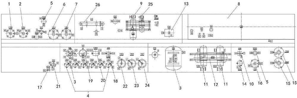
[0027] Such as figure 1 As shown, the integrated mobile natural gas liquefaction unit is composed of a heavy hydrocarbon removal unit, a decarbonization unit, a dehydration unit, a liquefaction unit, an amine liquid regeneration unit, a cooling unit and public works in a mobile and integrated manner, of which:

[0028] The heavy hydrocarbon removal unit includes activated carbon purification tower A1 and activated carbon purification tower B2, and activated carbon purification tower A1 is connected with activated carbon purification tower B2;

[0029] The decarbonization unit includes a raw material gas-liquid separator 3, a decarbonization tower group 4, a dust filter 5 and a separation tank. The raw material gas-liquid separator 3 is connected to the decarbonization tower group 4, and the bottom of the decarboniza...


PUM


Abstract

The invention discloses an integral mobile natural gas liquefaction device which is assembled in a mobile and integral manner. The device comprises a heavy hydrocarbon removal unit, a decarbonization unit, a dehydration unit, a liquefaction unit, an amine liquid regeneration unit, a cooling unit and a public project. The liquefaction device is characterized in that a mixed refrigerant and R22 are taken as cryogens to provide a refrigerating capacity for natural gas liquefaction; R134a and air cooling are combined to take the place of a traditional water cooling system, so rapid and convenient use of natural gas in areas which have not water supply and lack water becomes possible; and natural gas liquefaction can be achieved basically without pipeline laying on the ground. According to the invention, a sub-set mode is replaced by an integral machine mode, so floor space of equipment is further reduced; operations are more flexible; moving and assembly are convenient; operations and repair are simple; and consumption of manpower and materials is reduced. New technologies are used, so energy consumption is reduced; the degree of automation is greatly increased; the problem of water source lack is solved; and the device is applicable to various nonconventional gases and complicated terrains, so the utilization rate of the nonconventional gases can be increased greatly.

Description

[0001] Technical field: [0002] The invention belongs to a device for natural gas pretreatment and liquefaction, in particular to an integrated mobile natural gas liquefaction device. [0003] Background technique: [0004] Traditional LNG liquefaction plants have complex preparation procedures, high investment costs, long construction period, large floor area, complex process, high overall energy consumption, limited scope of application, and are not suitable for the use of gas in isolated wells and single wells in remote mountainous areas. . Due to the difficulty in developing unconventional natural gas, the geographical location of gas wells is complicated, and the laying of pipelines is out of reach. At present, most of the equipment in the existing technology is divided into different modules according to their functions, mainly modular mobile liquefaction equipment. , in which the refrigeration process mainly adopts a relatively mature nitrogen expansion process; the ab...

Claims


Application Information

Patent Timeline
Patent Type & Authority Applications(China)
IPC IPC(8): F25J1/02
CPCF25J1/0214F25J1/0228F25J1/0259F25J2210/60F25J2220/02F25J1/0022F25J1/0052F25J1/0215F25J1/0097F25J1/0268F25J2270/90
Inventor 龚晓科穆云飞赵阳王安胜幸涛陈宏伟唐刚杨敏王婷
Owner 宁夏凯添燃气发展股份有限公司
Why Eureka
Try Eureka