Erosion test device and method with capacity of controlling temperature, angle, flow velocity and time

A test device and angle technology, applied in the direction of measurement device, strength characteristics, test wear resistance, etc., can solve the problems of low degree of automation, waste of resources, small footprint, etc., to simplify the operation process, reduce labor costs, and automate high degree of effect

Active Publication Date: 2017-03-22
ZHEJIANG SCI-TECH UNIV
View PDF5 Cites 5 Cited by
  • Summary
  • Abstract
  • Description
  • Claims
  • Application Information

AI Technical Summary

Problems solved by technology

Aiming at the problems of pipeline damage and equipment damage caused by corrosive media erosion that are common in process industries, there are now a series of erosion and wear test devices, such as rotary erosion test devices, which have the advantages of small investment and floor space Small, the disadvantage is that there is a large deviation from the pipeline flow in real industry
The controllable factors of most erosion wear test devices are limited, and the erosion wear test cannot be carried out comprehensively. The degree of automation is low. At the same time, the corrosive medium cannot be recycled, and the waste of resources is serious.

Method used


Image

  • Erosion test device and method with capacity of controlling temperature, angle, flow velocity and time
  • Erosion test device and method with capacity of controlling temperature, angle, flow velocity and time
  • Erosion test device and method with capacity of controlling temperature, angle, flow velocity and time

Examples


Embodiment Construction

[0034] combine Figure 1 to Figure 4 , the technical solution of the present invention is described in detail:

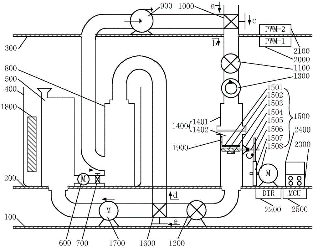
[0035] Such as figure 1 As shown, the present invention includes a first operating platform 100, a second operating platform 200 and a third operating platform 300 arranged from bottom to top, and a second hydraulic pressure sensor 1200, a diversion valve 1600 and a diversion valve 1600 are installed on the first operating platform 100. A flow pump 1700 , a thermostatic bottle 400 and an erosion device 1400 are installed on the second operating platform 200 , and a centrifugal pump 900 and a two-phase valve 1000 are installed on the third operating platform 300 .

[0036]The outlet port of the reagent bottle 500 is connected to the first inlet port of the buffer bottle 800 through the dosing pump 600 and the check valve 700 in turn, and the outlet port of the buffer bottle 800 is connected to the first inlet port of the two-phase valve 1000 through the centrifugal ...


PUM


Abstract

The invention discloses an erosion test device and method with capacity of controlling temperature, angle, flow velocity and time. An outlet of a reagent bottle is connected with a first inlet of a buffer bottle through a dosing pump and a check valve in sequence, an outlet of the buffer bottle is connected with a first inlet of a two-phase valve through a centrifugal pump, a second inlet of the two-phase valve is connected with outside atmosphere, an outlet of the two-phase valve is connected with an inlet of an erosion device through a first hydraulic sensor and a flow velocity sensor in sequence, an angle controller is connected and mounted on the erosion device, a temperature sensor is fixed on the inner side wall of the erosion device, an outlet of the erosion device is connected with an inlet of a diverter valve through a second hydraulic sensor, a first outlet of the diverter valve is connected with an inlet of the reagent bottle through a diversion pump, a fluid in a second outlet flows back to a second inlet of the buffer bottle; the reagent bottle, the dosing pump, the check valve and the buffer bottle are all placed in a constant-temperature bottle, and a heater is arranged in the constant-temperature bottle. With the adoption of the device and the method, erosion temperature, angle, flow velocity and time can be automatically regulated, labor cost is reduced, an operating process is simplified, reagents are recycled, and accordingly, resources are saved.

Description

technical field [0001] The invention relates to a test device and a test method, in particular to a temperature, angle, flow velocity and time controllable erosion test device and method. Background technique [0002] Pressure pipeline transportation has a wide range of applications and is widely used in petrochemical, coal chemical, biopharmaceutical and other process industries. Pressure pipelines usually have the characteristics of complex process, harsh operating conditions, and long operating cycle, and the conveying medium is often flammable, explosive, toxic, and harmful, especially the multiphase flow medium conveying system containing corrosive medium, involving multiphase Processes such as flow, cooling phase change, heat and mass transfer, etc., can easily lead to unplanned downtime accidents such as erosion and perforation of pressure pipes, leaking and bursting pipes in complex flow environments, and cause heavy losses. [0003] Erosion is the process of causin...

Claims


Application Information

Patent Timeline
IPC IPC(8): G01N3/56G01N3/02G01N17/00
CPCG01N3/02G01N3/567G01N17/00G01N2203/0222G01N2203/0242G01N2203/024G01N2203/0236G01N2203/0202
Inventor 金浩哲洪淼章剑强
Owner ZHEJIANG SCI-TECH UNIV
Why Eureka
Try Eureka