
Display panel and display device

A display panel and substrate technology, which is applied in the fields of instruments, nonlinear optics, optics, etc., can solve the problems of light energy reduction, high energy consumption of display devices, and low utilization rate

Active Publication Date: 2017-03-22
BOE TECH GRP CO LTD
View PDF4 Cites 59 Cited by
  • Summary
  • Abstract
  • Description
  • Claims
  • Application Information

AI Technical Summary

Problems solved by technology

[0003] This display method uses two layers of polarizers to polarize and analyze the light, resulting in a greatly reduced light energy and a light transmittance of only about 5%, resulting in problems such as high energy consumption and low utilization of the display device.

Method used


Image

  • Display panel and display device
  • Display panel and display device
  • Display panel and display device

Examples


Embodiment Construction

[0039] Specific embodiments of the present invention will be described in detail below in conjunction with the accompanying drawings. It should be understood that the specific embodiments described here are only used to illustrate and explain the present invention, and are not intended to limit the present invention.

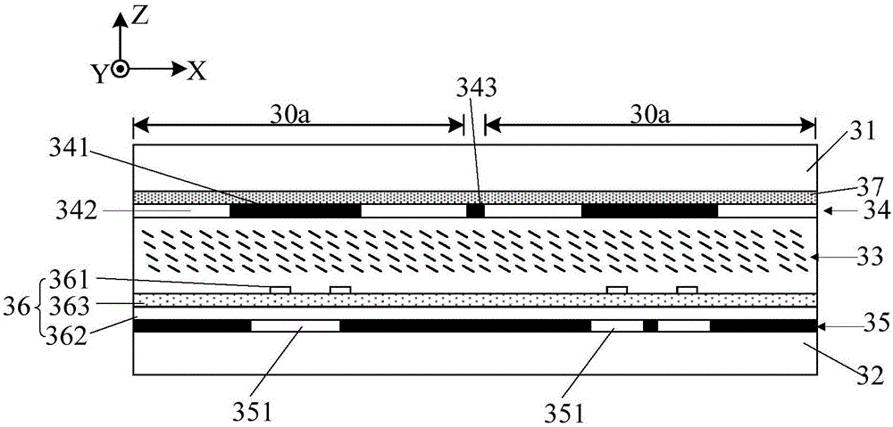
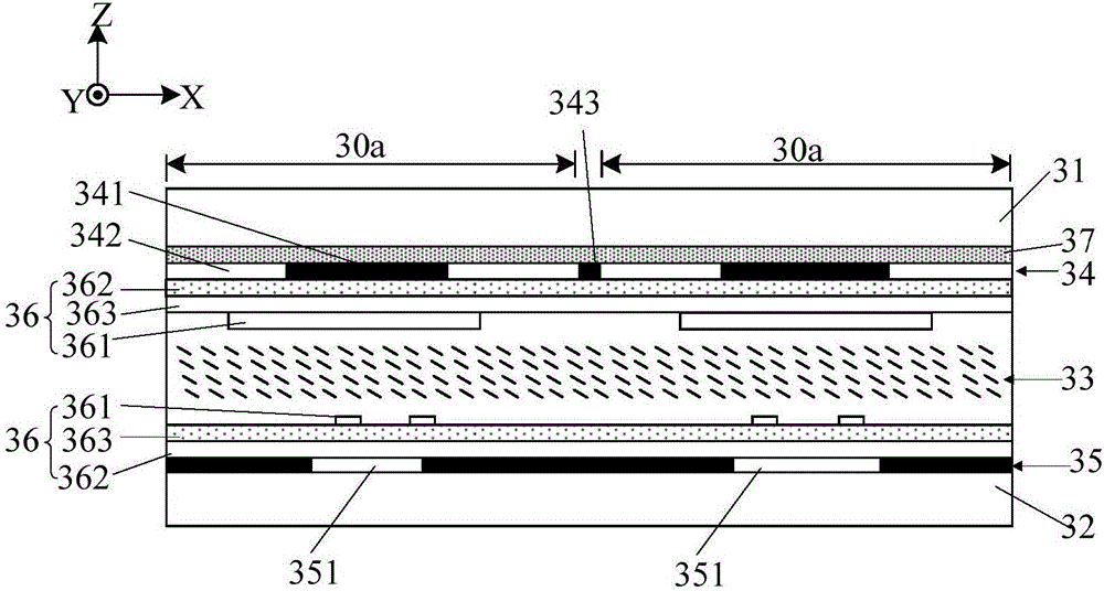
[0040] As an aspect of the present invention, a display panel is provided, such as Figure 2 to Figure 3b As shown, the display panel includes a first substrate 31 and a second substrate 32 oppositely arranged, and a liquid crystal layer 33 arranged between the first substrate 31 and the second substrate 32 . The display panel is divided into a plurality of pixel units 30a, and each pixel unit 30a includes at least one pixel portion. A first black matrix layer 34 is disposed on the first substrate 31 , and a second black matrix layer 35 is disposed on the second substrate 32 . The part of the first black matrix layer 34 corresponding to the pixel part includes...


PUM

PropertyMeasurementUnit
Thicknessaaaaaaaaaa

Abstract

The invention provides a display panel which comprises a first substrate, a second substrate and a liquid crystal layer. The first substrate and the second substrate are opposite to each other, and the liquid crystal layer is arranged between the first substrate and the second substrate; the display panel is divided into a plurality of pixel units, each pixel unit comprises at least one pixel, a first black matrix layer is arranged on the first substrate, a second black matrix layer is arranged on the second substrate; portions, which correspond to the pixels, of the first black matrix layer comprise shading portions and transmittance portions, the transmittance portions encircle the shading portions, and light transmission holes are formed in regions, which correspond to the shading portions, of the second black matrix layer; projection of the shading portions on the second black matrix layer covers the light transmission holes; electrode layers are arranged on at least one of the first substrate and the second substrate and are used for generating electric fields in the liquid crystal layer, and the electric fields of the various pixel units can be independently controlled. The invention further provides a display device correspondingly. The display panel and the display device have the advantages that contents can be displayed without polarizers, and accordingly light loss can be reduced.

Description

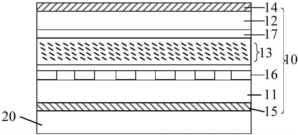
technical field [0001] The present invention relates to the field of display technology, in particular to a display panel and a display device. Background technique [0002] Traditional liquid crystal display devices such as figure 1 As shown, it includes a backlight module 20 and a display panel 10. The display panel 10 includes an array substrate 11, a color filter substrate 12 and a liquid crystal layer 13 between them. The outer sides of the array substrate 11 and the color filter substrate 12 are respectively provided with Two polarizers (upper polarizer 14 and lower polarizer 15 ) whose polarization directions are perpendicular to each other. A lower electrode 16 is arranged on the array substrate 11 , and an upper electrode 17 is arranged on the color filter substrate 12 , and an electric field for driving liquid crystal deflection is generated between the upper electrode 17 and the lower electrode 16 . When displaying, the lower polarizer 15 converts the natural li...

Claims


Application Information

Patent Timeline
IPC IPC(8): G02F1/1333G02F1/1335G02F1/13357
CPCG02F1/1333G02F1/133512G02F1/133514G02F1/133615G02F1/136222G02F1/133504G02F1/133617G02F1/1337G02F1/134309G02F1/13439G02F2202/36
Inventor 赵文卿董学陈小川王海燕陈祯祐李忠孝牛小辰王倩朱劲野
Owner BOE TECH GRP CO LTD
Learn More