Double parallel LED light source mechanism for exposure machine
A technology of LED light source and parallel light source, which is applied in the direction of optomechanical equipment, microlithography exposure equipment, photolithography exposure device, etc., can solve the problems of complex installation structure, high installation cost and high use cost, and achieve simple installation structure, The effect of reduced installation cost and convenient irradiation angle
- Summary
- Abstract
- Description
- Claims
- Application Information
AI Technical Summary
Problems solved by technology
Method used
Image

Examples
Embodiment Construction
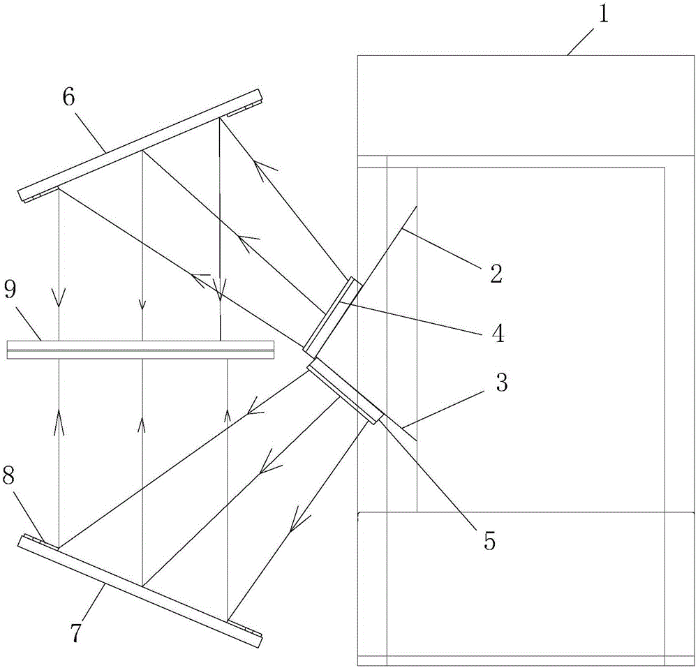
[0012] In this example, refer to figure 1 , the double LED parallel light source mechanism for the exposure machine includes two reflectors, i.e. the first reflector 6 and the second reflector 7, and the two reflectors are arranged on both sides of the exposure table 9 and are inclined towards the exposure table 9 settings; the light source adopts LED light sources, including two groups of LED light sources, that is, the first LED light source module 4 and the second LED light source module 5, wherein the first LED light source module 4 faces the first reflector 6, and the emitted The light is directly irradiated to the first reflector 6 and is reflected by the first reflector 6 and is irradiated to the exposure table 9 as parallel light; the second LED light source module 5 faces the second reflector 7, and the light emitted by it is directly irradiated to the second reflector 7. The reflector 7 is reflected by the second reflector 7 and irradiates the exposure table 9 as par...
PUM
 Abstract
Description
Claims
Application Information
 - R&D
- Intellectual Property
- Life Sciences
- Materials
- Tech Scout
- Unparalleled Data Quality
- Higher Quality Content
- 60% Fewer Hallucinations
Browse by: Latest US Patents, China's latest patents, Technical Efficacy Thesaurus, Application Domain, Technology Topic, Popular Technical Reports.
© 2025 PatSnap. All rights reserved.Legal|Privacy policy|Modern Slavery Act Transparency Statement|Sitemap|About US| Contact US: help@patsnap.com