Software-controlled base line regulating circuit

A technology for regulating circuits and software control, applied in control/regulating systems, regulating electrical variables, instruments, etc., can solve problems such as large redundancy, high cost, and large ripple, and meet the requirements of DC bias ripple requirements, low cost, and stable voltage

Active Publication Date: 2017-03-22
上海中嘉衡泰医疗科技有限公司
View PDF5 Cites 3 Cited by
  • Summary
  • Abstract
  • Description
  • Claims
  • Application Information

AI Technical Summary

Problems solved by technology

Among them, DAC is the easiest way to think of, but the redundancy is large, the cost is obviously high, and the signal operation circuit is required to generate the default voltage value, so as to ensure that the analog signal will not be affected when the system is powered on and the software is not yet controlled. Significantly beyond the input range of the ADC
In addition, the required analog voltage can also be obtained by using PWM plus low-pass filtering, but for accurate measurement, the ripple is often too large, and there is also the need to additionally solve the problem of the default voltage value

Method used


Image

  • Software-controlled base line regulating circuit
  • Software-controlled base line regulating circuit

Examples


Embodiment 1

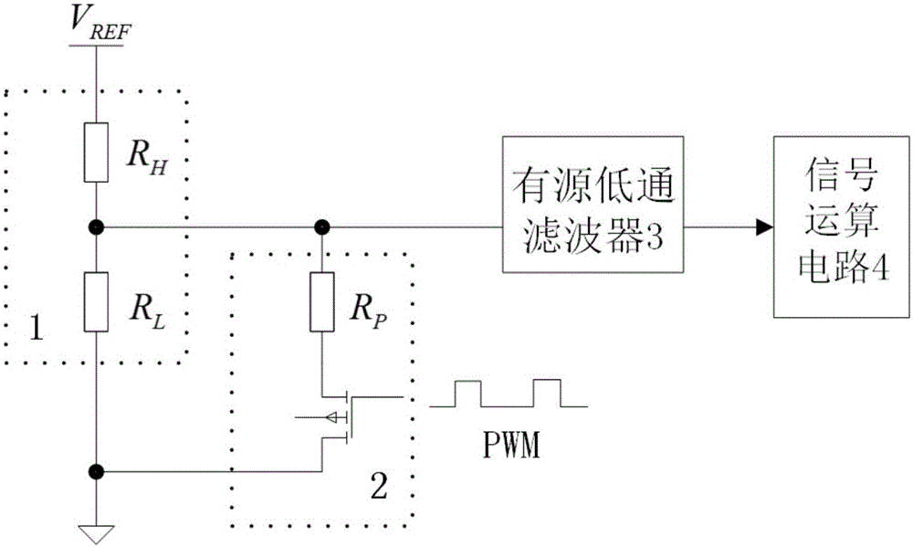
[0028] The software-controlled baseline adjustment circuit designed in this embodiment is as follows: figure 1 As shown, it consists of four parts as a whole: basic voltage division branch 1, parallel branch 2 controlled by PWM, active low-pass filter 3 and signal operation circuit 4. The basic voltage dividing branch 1 is a basic circuit for generating a DC bias voltage. Obtain a stable DC voltage V from the analog circuit part ref , such as obtained from a voltage reference chip, or using the power supply voltage output by a power regulator chip. Use two resistors R with better temperature characteristics for this DC voltage H and R L Divide the voltage to get a basic DC bias voltage, denoted as V H .

[0029] The parallel branch 2 controlled by PWM is composed of a resistor R with better temperature characteristics P It is composed of an N-type MOSFET in series, and this branch is connected in parallel with the low-voltage terminal resistance R of the basic voltage di...

Embodiment 2

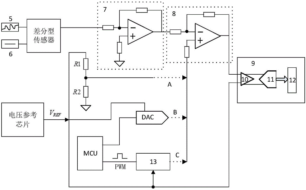
[0034] figure 2 It is a certain application occasion of the baseline adjustment circuit of the present invention, and is compared with the existing baseline adjustment scheme.

[0035] exist figure 2 In the application of the differential sensor, the difference between the measured object 5 and the standard reference point 6 is converted into a voltage signal. The dc component also fluctuates slowly over time, requiring accurate measurement of all fluctuations in this signal.

[0036] The role of the pre-amplification circuit 7 is to amplify the signal amplitude output by the sensor to match the input range of the ADC, fully utilizing but not exceeding the conversion range of the ADC.

[0037] The function of the signal operation circuit 8 is mainly to perform DC bias on the measured signal, so that the voltage fluctuation range of the measured signal is within the input range of the ADC.

[0038]On-chip integrated PGA ADC9, for different measured objects, the PGA10 integ...

Embodiment 3

[0046] The difference from Embodiment 1 is that the parallel branch 2 controlled by PWM is composed of a resistor R with better temperature characteristics P It is composed of a P-type MOSFET in series, and this branch is connected in parallel with the high-voltage end resistance R of the basic voltage divider branch 1 H superior. The 2 resistors R of the basic voltage divider branch H and R L and the shunt branch resistance R P , these three resistors need to be calculated according to the range that needs to be adjusted for the baseline in practical applications. Since the parallel connection methods of Embodiment 1 and Embodiment 3 are different, the calculated resistance values ​​and adjustment methods are different. All the other are identical with embodiment 1.


PUM


Abstract

The invention relates to a software-controlled base line regulating circuit. The software-controlled base line regulating circuit comprises a basic divider branch, a PWM-controlled parallel branch, an active low-pass filter circuit and a signal operation circuit; the basic divider branch comprises two direct-current divider resistors which are connected in series, the PWM-controlled parallel branch is connected with one of the direct-current divider resistors in parallel, and the active low-pass filter circuit and the signal operation circuit are sequentially connected to the middle point of the two direct-current divider resistors; the PWM-controlled parallel branch is provided with a resistors Rp and MOSFET which are connected in series, on-off of the MOSFET is controlled by an external PWM signal, PWM duty cycle changes are controlled by software, and then the volume of output voltage of the base line regulating circuit is regulated. Compared with the prior art, the circuit is extremely simple and effective and low in cost, and the regulating range is easily designed to exactly meet the requirements without redundance.

Description

technical field [0001] The invention relates to a signal processing circuit, in particular to a software-controlled baseline adjustment circuit. Background technique [0002] In the process of small signal measurement, the signal conditioning circuit is usually necessary. In order to make the analog signal best match the input range of the AD converter, the signal conditioning circuit usually needs to amplify or reduce the amplitude of the original signal output by the sensor. The baseline is raised or lowered. Wherein, raising or lowering the baseline means raising or lowering the overall signal, that is, adding or subtracting a DC bias. [0003] In most circuit designs, a fixed DC bias is sufficient to meet the design requirements. According to the specific size of the measured signal and the input range of the AD converter, calculate the required DC offset, and then use a standard reference voltage and signal operation circuit to add or subtract a fixed DC voltage for t...

Claims


Application Information

Patent Timeline
Patent Type & Authority Applications(China)
IPC IPC(8): G05F1/56
CPCG05F1/561
Inventor 贾林壮张捷赵振华
Owner 上海中嘉衡泰医疗科技有限公司
Why Eureka
Try Eureka